
Single Photon-Counting Imaging System and Method Thereof

a single-photon counting and imaging system technology, applied in the field of ultra-weak light detection, can solve the problems of weak sensitivity, high cost of array detectors for single-photon detection level, and inability to realize, and achieve the effects of high detection sensitivity, high resolution and high resolution

Inactive Publication Date: 2013-12-26
NAT SPACE SCI CENT CAS
View PDF0 Cites 9 Cited by
  • Summary
  • Abstract
  • Description
  • Claims
  • Application Information

AI Technical Summary

Benefits of technology

The invention is a method and device that uses a single-photon detector and a digital light processing (DLP) system to capture ultra-weak light. The method uses a combination of a DMD, a first lens, and a second lens to convert two-dimensional image data into a one-dimensional data sequence, allowing for compressive sampling of the signals to be measured. The captured light is then filtered and imaged through the first lens. The second lens controls the focusing of the photons, and a light attenuator is used to prevent saturation of the detector. The technology solves the problem of low sensitivity and narrow wavelength range of traditional detectors, and can be applied in various fields such as biological self-illumination, medical diagnosis, and quantum electronics.

Problems solved by technology

However, the array detector for the single-photon detection level is expensive and can be realized in only a few wave bands, and furthermore it has weak sensitivity, and so there exists the contradiction between technical immaturity and strong demand of two-dimensional imaging of an ultra-weak light object.

Method used


Image

  • Single Photon-Counting Imaging System and Method Thereof
  • Single Photon-Counting Imaging System and Method Thereof
  • Single Photon-Counting Imaging System and Method Thereof

Examples


Embodiment Construction

[0044]The invention is further illustrated in detail in conjunction with the drawings.

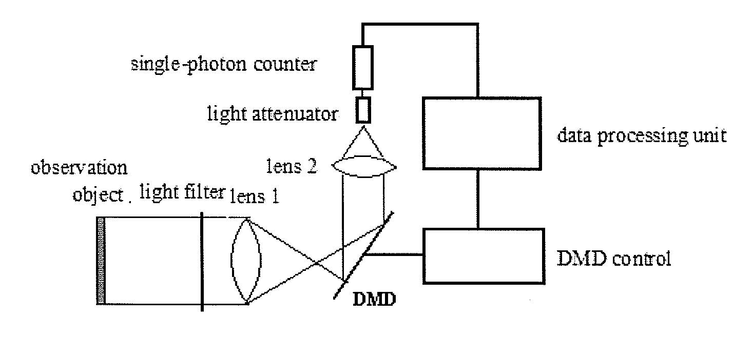
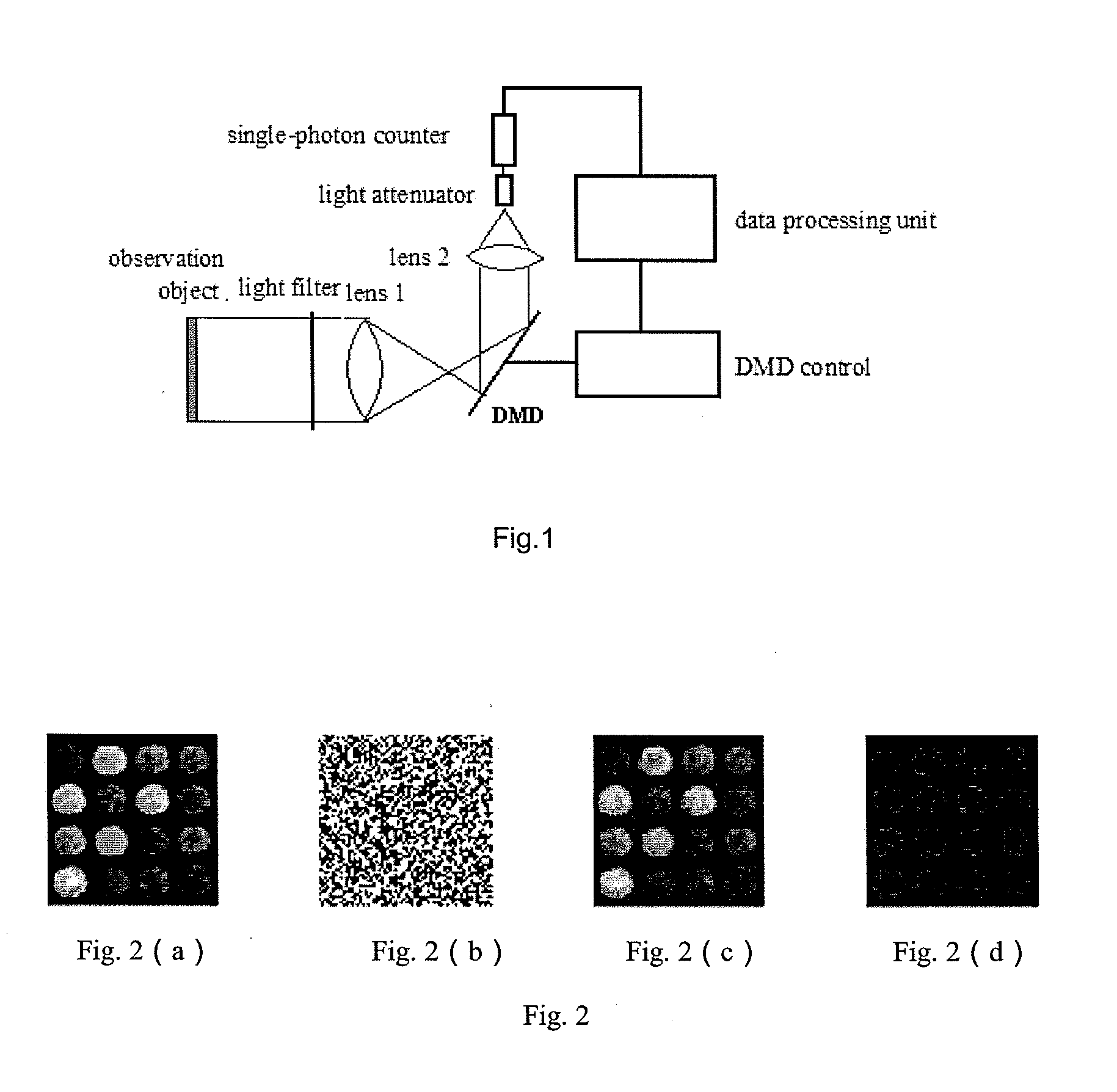
[0045]As shown in FIG. 1, the stray light in an ultra-weak light emitted by an observation object is filtered by a light filter, after which the ultra-weak light is imaged at a DMD control system through a first lens 1. The DMD control system controls the probability that the photons are reflected to a second lens 2 and the second lens 2 controls the focusing of the photons. A light attenuator is used for attenuating light to the working range of a single-photon detector when the light is over intensive. A single-photon counter counts the number of photons in a certain period of time, and the value of the number obtained can be converted into the probability of detected photons counts and is used as a measured value. Finally a data processing unit reconstructs a photon density image according to the measured value and the measurement matrix on the DMD control system through an optimization algorith...


PUM


Abstract

The invention relates to a single-photon counting imaging system and a single-photon counting imaging method. The system comprises a optical filter, a first lens, a digital micro-mirror device (DMD) control system, a second lens, a single-photon counter and a data processing unit, where the DMD together with the first lens and the second lens are used for converting two-dimensional image data into a one-dimensional sequence to complete sampling of measured signals; the ultra-weak light is filtered by the optical filter, after which the ultra-weak light image onto the DMD through the first lens, and the DMD control system controls the probability of the photons reflected to the second lens and the second lens controls the focusing of the photons; and the data processing unit together with the single-photon counter to complete sparse reconstruction, and the data processing unit converts the number of photons counted by the single-photon counter within a certain period of time into the probability of detected photon counts, as the measured value, and a photon density image is reconstructed by adopting an optimization algorithm based on the measurement matrix on the DMD and the measured value, thereby solving out the two-dimensional image.

Description

FIELD OF THE INVENTION[0001]The invention relates to the technical field of ultra-weak light detection, in particular to a single-photon counting imaging system and a single-photon counting imaging method. High-quality two-dimensional imaging of an ultra-weak light object can be realized using a point detector by adopting the compressed sensing theory and the digital light processing (DLP) technology.BACKGROUND OF THE INVENTION[0002]Common imaging device acquires an image by recording the light intensity and the position of a certain point on an observation object. When the light intensity of the observation object is attenuated to a certain extent and reaches a single-photon level, discrete pulse signals are formed. A single photon, as an ultra-weak light, is regarded as the indivisible minimum energy unit of light, the detectable limit as well. The single-photon detection technology is applied in the fields of biological self-illumination, medical diagnosis, nondestructive materia...

Claims


Application Information

Patent Timeline
IPC IPC(8): G01J1/44
CPCG01J1/44G01J1/0414G01J1/42G01J2001/442
Inventor ZHAI, GUANGJIEDU, KEMINGWANG, CHAOYU, WENKAI
Owner NAT SPACE SCI CENT CAS
Learn More