Material for organic electroluminescence device, and organic electroluminescence device using the same

Active Publication Date: 2014-01-02
IDEMITSU KOSAN CO LTD
View PDF2 Cites 28 Cited by
  • Summary
  • Abstract
  • Description
  • Claims
  • Application Information

AI Technical Summary

Benefits of technology

[0036]one or more organic thin film layers including

Problems solved by technology

In the case of fluorescent type, due to using the emitting by singlet excitons, the internal quantum efficiency is regarded as having a limitation of 25%.
In particular, as for a phosphorescent organic EL device, it is known that a high-performance device cannot be obtained by simple application of the technology of a fluorescent device due to its emission

Method used


Image

  • Material for organic electroluminescence device, and organic electroluminescence device using the same
  • Material for organic electroluminescence device, and organic electroluminescence device using the same
  • Material for organic electroluminescence device, and organic electroluminescence device using the same

Examples


synthesis example 1

Synthesis of Compound H1

[0254]

[0255]Under an argon stream, Intermediate 2 (2.3 g, 7.2 mmol), Intermediate 5 (3.2 g, 8.6 mmol), tris(dibenzilidene acetone)dipalladium (Pd2(dba)3; 0.26 g, 0.29 mmol), tri-t-butylphosphonium tetrafluoro borate (P(tBu)3.HBF4; 0.21 g, 0.72 mmol), sodium t-butoxide (NaOtBu; 1.4 g, 14 mmol) and anhydrous xylene (40 mL) were sequentially charged and the mixture was heated under reflux for 8 hours.

[0256]After the reaction solution was heated to room temperature, the organic phase was separated, and the organic solvent was distilled away under reduced pressure. The residue obtained was purified by means of silica gel column chromatography to obtain 3.6 g of yellowish white solids (Compound H1).

[0257]The result of FD-MS for the compound obtained is shown below.

FDMS, calcd for C47H30N4=650, found m / z=650 (M+)

synthesis example 2

Synthesis of Compound H2

[0258]

[0259]Compound H2 was synthesized in the same manner as in the synthesis of Compound H1 in Synthesis Example 1 (6), except that Intermediate 4 was used instead of Intermediate 5.

[0260]The result of FD-MS for the compound obtained is shown below.

FDMS, calcd for C41H26N4=574, found m / z=574 (M+) [0169]

Preparation of Organic EL Device and Evaluation of Emitting Performance

example 1

(Fabrication of Organic EL Device)

[0261]A glass substrate, measuring 25 mm×75 mm×1.1 mm thick, with an ITO transparent electrode (manufactured by Geomatics Co.) was subjected to ultrasonic cleaning in isopropyl alcohol for 5 minutes and then UV ozone cleaning for 30 minutes.

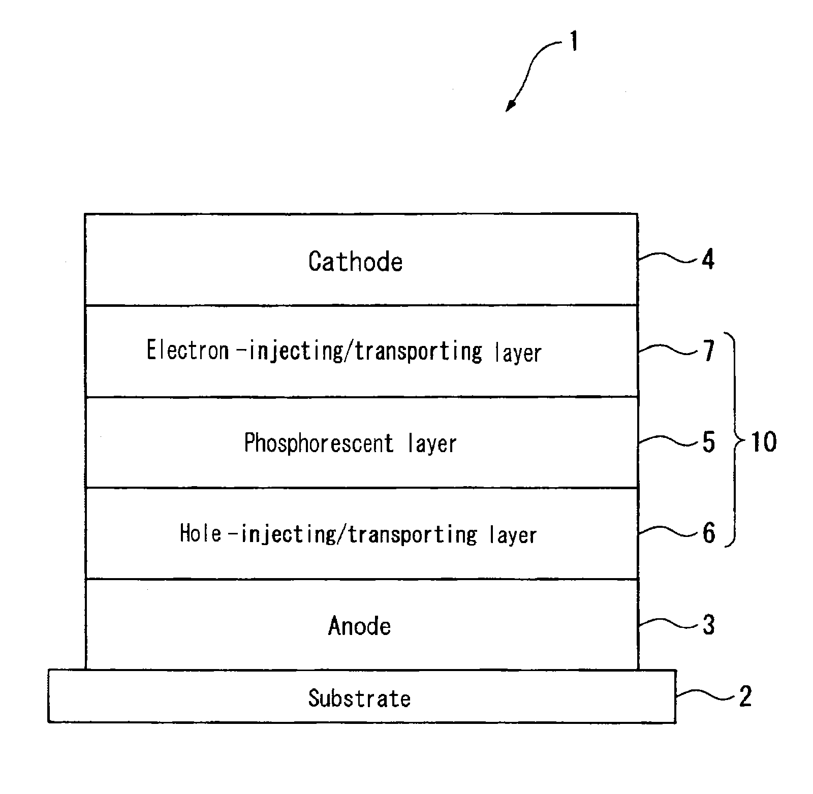
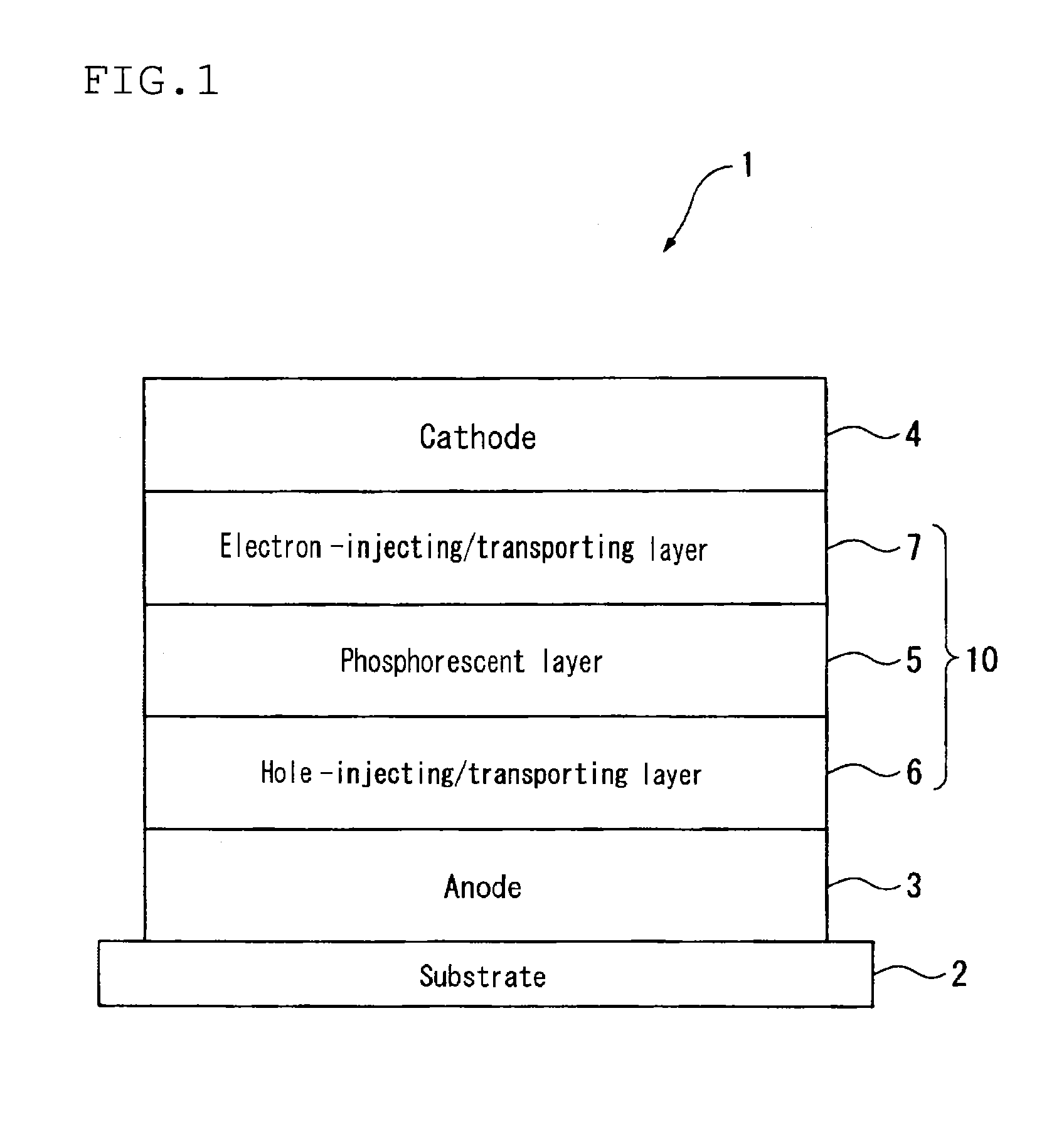
[0262]The cleaned glass substrate with transparent electrode lines was mounted on a substrate holder in a vacuum deposition device. First, a 5 nm thick film of the following acceptor compound C-1 was formed by deposition on the surface where the transparent electrode lines were formed, so as to cover the transparent electrode. On the film of compound C-1, as a first hole-transporting material, the following aromatic amine derivative (compound X1) was deposited to form a first hole-transporting layer having a thickness of 65 nm. Subsequent to the formation of the first hole-transporting layer, as a second hole-transporting material, the following aromatic amine derivative (compound X2) was deposited to form a seco...


PUM


Abstract

A material for an organic electroluminescence device represented by the following formula (I):
    • wherein X1 to X8 are a nitrogen atom, CH, CHal or CRa; Az is a nitrogen-containing six-membered ring or a fused polycyclic group including a nitrogen-containing six-membered ring; W is an aromatic hydrocarbon group having 6 to 30 ring carbon atoms which is substituted by at least one cyano group or a heterocyclic group having 5 to 30 ring atoms which is substituted by at least one cyano group.

Description

TECHNICAL FIELD[0001]The invention relates to a material for an organic electroluminescence device, and an organic electroluminescence device using the same.BACKGROUND ART[0002]When a voltage is applied to an organic electroluminescence device (also hereinafter referred to as an organic EL device), holes and electrons are injected into an emitting layer from an anode and a cathode, respectively. In the emitting layer, the injected holes and electrons are recombined to form excitons. At this time, according to electron spins statistics, singlet excitons and triplet excitons are generated in a rate of 25%:75%. The emitting type is classified into two groups, i.e. fluororescent type and phosphorescent type, according to the emitting system. In the case of fluorescent type, due to using the emitting by singlet excitons, the internal quantum efficiency is regarded as having a limitation of 25%. On the other hand, in the case of phosphorescent type, emission by triplet excitons is used. A...

Claims


Application Information

Patent Timeline
IPC IPC(8): H01L51/00
CPCC09K11/06H01L51/0067H01L51/0072C07D403/04H01L51/50C09K2211/1007C09K2211/1011C09K2211/1029C09K2211/1044C09K2211/1059C09K2211/1088C09K2211/1092C09B57/00H10K85/654H10K85/6572
Inventor MIZUKI, YUMIKOYABUNOUCHI, NOBUHIROINOUE, TETSUYAHIBINO, KUMIKONISHIMURA, KAZUKI
Owner IDEMITSU KOSAN CO LTD
Why Eureka
Try Eureka