

Organic electroluminescent element, method for manufacturing organic electroluminescent element, and coating liquid for electron injection and transport layer
a technology of electroluminescent elements and organic electroluminescent elements, which is applied in the direction of non-metal conductors, conductors, thermoelectric devices, etc., can solve the problems of large-scale vacuum system, difficult uniform control of film thickness, and poor production efficiency, and achieves the effect of longer service life and high efficiency
- Summary
- Abstract
- Description
- Claims
- Application Information
AI Technical Summary
Benefits of technology
Problems solved by technology
Method used
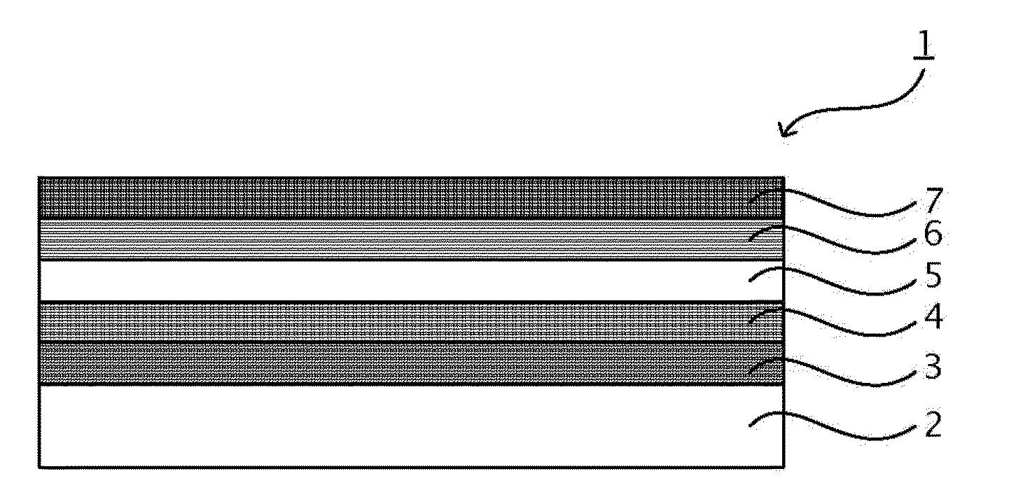
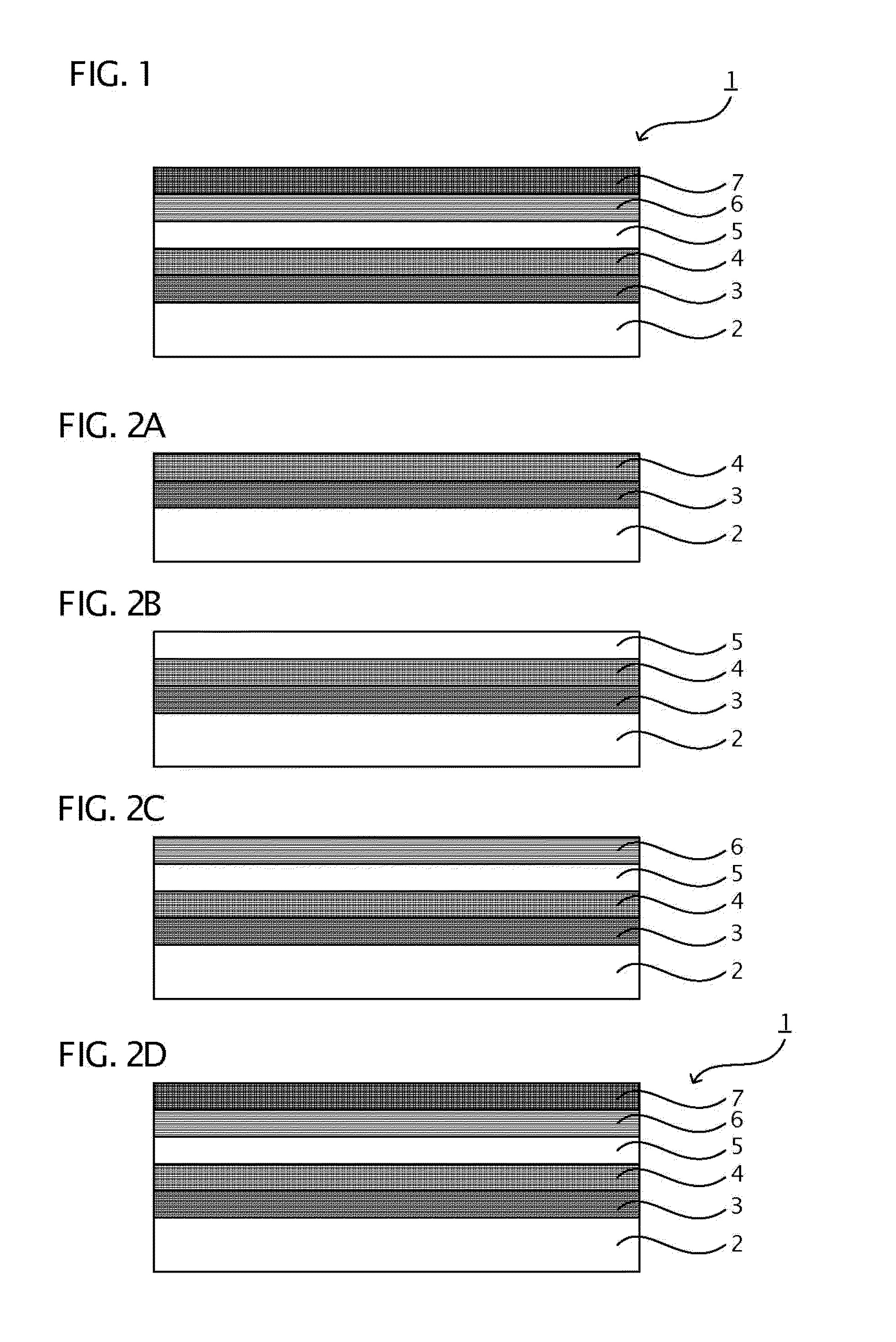
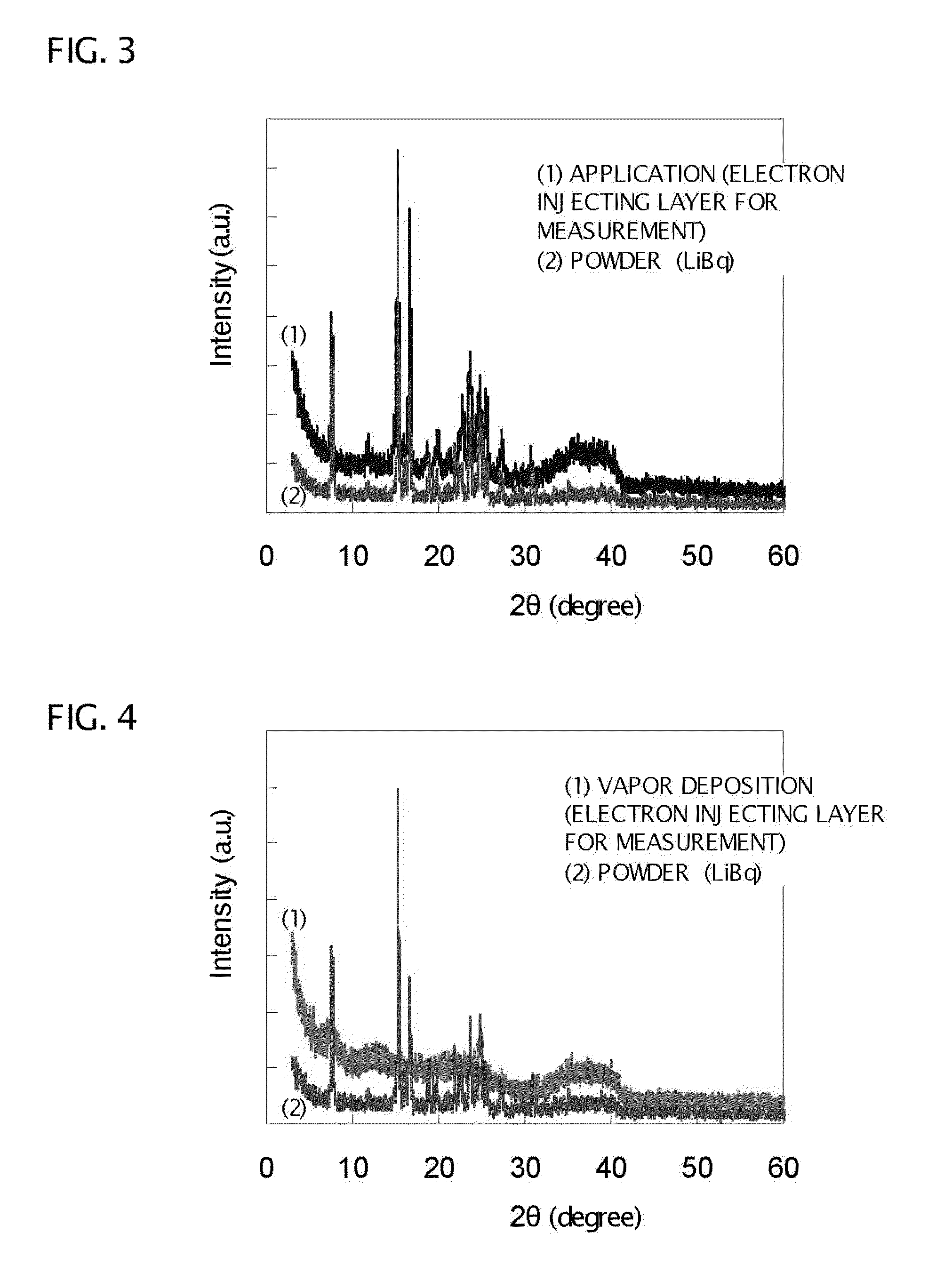
Image

Examples
example 1
[0195]As an anode, an ITO of 150 nm thick was formed in a striped pattern on a glass substrate of 25 mm×25 mm×0.7 mm (manufactured by Sanyo Vacuum Industries Co., Ltd). This ITO substrate was subjected to ultrasonic cleaning in the order of a neutral detergent and ultrapure water, and to UV ozone cleaning for 10 minutes.
[0196]As a hole injecting layer, a PEDOT-PSS thin film (thickness: 30 nm) was formed on the ITO substrate. The PEDOT-PSS thin film was formed by applying a PEDOT-PSS solution (manufactured by Bayer AG, Baytron P AI 4083™). After the application of the solution, drying at 200° C. for 30 minutes was carried out with the use of a hot plate in order to evaporate the solvent.
[0197]As a hole injection / transport layer, a conjugated polymer material, poly[(9,9-dioctylfluorenyl-2,7-diyl)-co-(4,4′-(N-(4-sec-but ylphenyl))diphenylamine)] (TFB) thin film (thickness: 10 nm) was formed on the hole injecting layer. The TFB thin film was formed in such a way that a solution of TFB d...
example 2
[0202]Except that LiBPh represented by the following formula was used instead of LiBq to form an electron injection and transport layer, an organic EL element was prepared in the same way as in Example 1.
reference example 1
[0203]Except that Ca was used instead of LiBq to form an electron injection and transport layer, an organic EL element was prepared in the same way as in Example 1.
[Evaluation]
[0204]A voltage was applied between the anodes and cathodes of the organic EL elements according to Examples 1 and 2 and Reference Example to measure current efficiencies at 10 mA / cm2, Table 4 shows the relative ratios to the current efficiency for Reference Example 1 as 100.
TABLE 4Current EfficiencyVoltage (V)(Relative Ratio)Reference7.0100Example 1Example 18.3104Example 28.4100
[0205]From Table 4, the organic EL elements with the use of the organic boron compound according to Examples 1 and 2 exhibit favorable characteristics as in the organic EL element with the use of Ca according to Reference Example.
PUM
 Abstract
Description
Claims
Application Information