Lithium ion rechargeable battery and process for producing the lithium ion rechargeable battery

a lithium ion rechargeable battery, multi-layer technology, applied in the direction of cell components, final product manufacturing, sustainable manufacturing/processing, etc., can solve the problems of not always forming a useful reaction product, the interface resistance or adhesion between the intermediate layer and the electrode layer or the intermediate layer and the electrolyte layer is not improved, and the overall electric characteristics and mechanical characteristics of the battery are not improved. , to achieve the effect of reducing the internal resistance of the battery, reducing the interface resistance resistan

Active Publication Date: 2014-01-16
NAMICS CORPORATION
View PDF4 Cites 5 Cited by
  • Summary
  • Abstract
  • Description
  • Claims
  • Application Information

AI Technical Summary

Benefits of technology

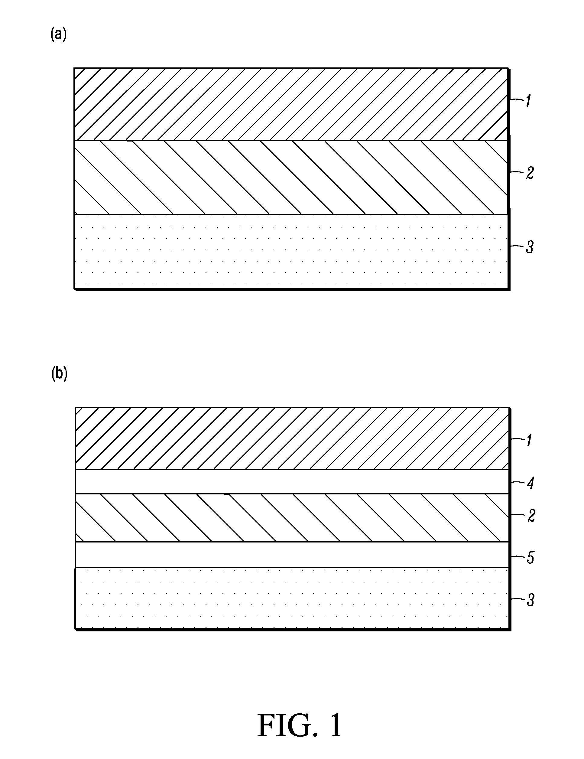
[0047]According to the present invention (1), or (5) to (7), or (10), and (22), the interface bonding of the multilayered product of the lithium ion rechargeable battery is strengthened, and the interface resistance is reduced at the same time, whereby battery internal resistance can be reduced, and charging and discharging cycle characteristics can be improved.
[0048]According to the invention (2), (3), (8), (9), (23), or (24), the following advantages are exerted.1. The mixing ratio between the active material and the conductive material is within a range of 20:80 to 65:35 in the area ratio, whereby the electrode structure is the structure in which the active material is supported in the conductive matrix, and the conductive matrix assists the active material of a low electric conductivity to carry current. Thus, the present invention is advantageous in improving battery performance such as a reduction in impedance and an increase in ampere-hour capacity.2. Because the electrode layer functions as the active material layer and the current collector layer before in a single layer, no current collector layer is necessary, and the present invention is advantageous in a simplified process steps, reductions in manufacture costs, prevention of sheet attack, and the like.3. The electrode is formed in the structure in which the active material is supported in the conductive matrix, whereby the active material and the conductive material are entangled with each other. Thus, expansion caused by charging and discharging and the removal of the active material and the conductive material because of contraction can be suppressed, and the present invention is advantageous in improving charging and discharging cycle characteristics.4. The active material, which is difficult to be adopted in the past because of its too small electric conductivity, is supported in the conductive matrix, whereby the active material can be adopted as an excellent active material for the electrode material of the lithium ion rechargeable battery.
[0049]According to the inventions (11) to (13), at the interface of the electrode layer and the electrolyte layer, the formation of a useful reaction product that functions as the active material or the electrolyte can be promoted.
[0050]According to the invention (14), the ionic conductance in the electrolyte layer can be improved.
[0051]According to the invention (15), the ionic conductance in the electrolyte layer can be made optimum.
[0052]According to the invention (16), a small-sized lithium ion rechargeable battery of large capacity with low internal resistance and high performance can be produced.

Problems solved by technology

Therefore, it cannot be said that a useful reaction product is not always formed on the intermediate layer.
In addition, even though interface resistance between the active material and the electrolyte is reduced inside the intermediate layer, it cannot be said that because the product is not baked after laminated, the interface resistance or adhesion between the intermediate layer and the electrode layer or the intermediate layer and the electrolyte layer is not improved, and the overall electric characteristics and mechanical characteristics of the battery are not improved.
In addition, because of the necessities of conducting process steps of coating and drying the intermediate layer, problems arise that process steps are complicated and manufacture costs are expensive.
In other words, it is not the technique to form a useful intermediate layer by baking.

Method used

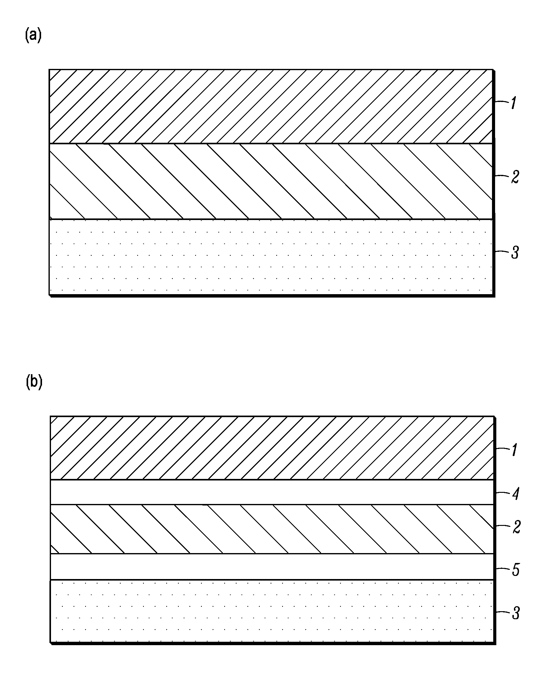

Image

  • Lithium ion rechargeable battery and process for producing the lithium ion rechargeable battery
  • Lithium ion rechargeable battery and process for producing the lithium ion rechargeable battery
  • Lithium ion rechargeable battery and process for producing the lithium ion rechargeable battery

Examples


example 1

[0171]Hereinafter, examples are used to describe the present invention in detail. In addition, the expression “parts” means parts by weight, unless otherwise specified.

[0172](Preparation of a Positive Electrode Paste)

[0173]For the positive active material, LiMn2O4 prepared by a method described below was used.

[0174]Li2CO3 and MnCO3 were used as starting materials, and weighted to be at a mol ratio 1:4, water was used as a solvent to conduct wet blending in a ball mill for 16 hours, and then the mixture was dewatered and dried. The resulting powder was calcined in the air for two hours at a temperature of 800° C. The calcined product was roughly crushed, water was used as a solvent to conduct wet blending in a ball mill for 16 hours, and then the mixture was dewatered and dried to obtain a positive active material powder. The BET value of this powder was 13.4 m2 / g. An X-ray diffraction device was used to confirm that the composition of the prepared powder was LiMn2O4.

[0175]For a posi...

example 2

[0194]XRD analysis was used to study reactions between the solid electrolyte, the positive active material, and the negative active material by baking and to identify the reaction product.

[0195]FIG. 3 is a work flowchart depicting a study experiment to study reactions between the solid electrolyte material and the active material.

[0196]A study method was conducted according to the process steps shown below.

(1) The solid electrolyte, the positive active material, and the negative active material were mixed in a mortar.

(2) The mixed powders were shaped in a mold to prepare a disk.

(3) The temperature of the prepared disk was increased to a set temperature at the rate of temperature rise of 200° C. / hr, kept for two hours, and then allowed to stand to cool. The set temperature was temperatures of 500, 600, 700, 800, 900, 960, 1000, and 1050° C.

(4) The baked disk was crushed in a mortar to form a sample.

(5) Substances were identified by XRD.

[0197]FIG. 4 shows XRD patterns of samples that ...

example 3

[0199]XRD analysis was conducted by a method similar to that of Example 2, reactions between the solid electrolyte and the active material by baking were studied, and reaction products were identified.

[0200]FIG. 10 shows XRD patterns of samples that a solid electrolyte Li3.5Si0.5P0.5O4 and an active material LiMn1.5Co0.5O4 were mixed and then baked. It is seen that in the pattern before baked and the pattern of baking at a temperature of 600° C., only the peaks of the solid electrolyte Li3.5Si0.5P0.5O4 and the active material LiMn1.5CO0.5O4 are observed, whereas in the patterns of baking at temperatures of 700° C. or greater, the peak of LiMnCoO4, which is a reaction product, is observed. LiMnCoO4 is a substance that functions as the active material.

[0201]FIG. 11 shows XRD patterns of samples that a solid electrolyte Li3.5Si0.5P0.5O4 and an active material LiMn1.5Ni0.5O4 were mixed and then baked. It is seen that in the pattern before baked and the patterns of baking at temperatures...


PUM

PropertyMeasurementUnit
temperaturesaaaaaaaaaa
temperatureaaaaaaaaaa

Abstract

Conventional ion rechargeable batteries having an electrode layer on an electrolyte layer suffer from an impurity layer formed at the interface, degrading performance. Conventional batteries with no such impurity layer have a problem of weak interface bonding. In the present invention, in a baking process step after an electrode layer is laminated on an electrolyte layer, materials for an electrode layer and an electrolyte layer are selected such that an intermediate layer formed of a reaction product contributing to charging and discharging reactions is formed at the interface of the electrode layer and the electrolyte layer. In addition, a paste that an active material is mixed with a conductive material at a predetermined mixing ratio is used to form a positive electrode layer and a negative electrode layer. Reductions in electrode resistance and interface resistance and improvement of charging and discharging cycle characteristics are made possible.

Description

[0001]This application is a division of U.S. Ser. No. 12 / 599,941, filed Dec. 30, 2009, which is a U.S. National Stage Application of PCT / JP2008 / 058616, filed May 9, 2008, which applications are incorporated herein by reference.TECHNICAL FIELD[0002]The present invention relates to a multilayer all solid state lithium ion rechargeable battery including a multilayered product formed of a positive electrode layer, an electrolyte layer, and a negative electrode layer, and a method of manufacture of the same.BACKGROUND ART[0003]Patent Document 1: JP 2007-5279 A[0004]Patent Document 2: JP 2000-164252 A[0005]Patent Document 3: JP 2004-281316 A[0006]Patent Document 4: JP H06-9141 B[0007]Patent Document 5: JP 2001-210360 A[0008]Patent Document 6: JP 2001-351615 A[0009]Non-Patent Document 1: J. Power Sources, 81-82, (1999), 853[0010]Non-Patent Document 2: J. Electrochem. Soc., 124, (1977), 1240-1242[0011]In recent years, the development of electronics techniques is remarkable, and portable ele...

Claims


Application Information

Patent Timeline
Patent Type & Authority Applications(United States)
IPC IPC(8): B29C65/02H01M4/13H01M4/485H01M4/505H01M4/62H01M10/052H01M10/0562H01M10/0585
CPCB29C65/02H01M4/366H01M4/485H01M4/505H01M4/624H01M10/0525H01M10/0562Y02E60/10Y10T29/49112Y02P70/50H01M10/056
Inventor BABA, MAMORUIWAYA, SHOICHIMASUMURA, HITOSHISAKAI, NORIYUKIFUJITA, TAKAYUKISASAGAWA, HIROSHISATO, HIROSHI
Owner NAMICS CORPORATION
Why Eureka
Try Eureka