Thermal barrier coating for industrial gas turbine blade, and industrial gas turbine using the same

a technology of industrial gas turbine blades and thermal barrier coatings, which is applied in the direction of solid-state diffusion coatings, superimposed coating processes, machines/engines, etc., can solve problems such as mechanical properties being damaged, and achieve the effects of improving the strength reliability of the turbine blade, preventing element diffusion, and improving durability against thermal fatigu

Inactive Publication Date: 2014-01-16
HOKKAIDO UNIVERSITY +1
View PDF3 Cites 4 Cited by
  • Summary
  • Abstract
  • Description
  • Claims
  • Application Information

AI Technical Summary

Benefits of technology

[0013]The present invention can prevent element diffusion into the substrate with the use of the diffusion barrier layer, and improve durability against thermal fatigue due to thermal cycles and durability against mechanical fatigue. Thus the present invention makes it possible to improve the strength reliability of the turbine blade for industrial gas turbine, and increase the lifetime of the turbine blade for industrial gas turbine.

Problems solved by technology

These are detrimental to mechanical property important for gas turbine blades such as creep strength and fatigue strength.

Method used


Image

  • Thermal barrier coating for industrial gas turbine blade, and industrial gas turbine using the same
  • Thermal barrier coating for industrial gas turbine blade, and industrial gas turbine using the same
  • Thermal barrier coating for industrial gas turbine blade, and industrial gas turbine using the same

Examples


example 1

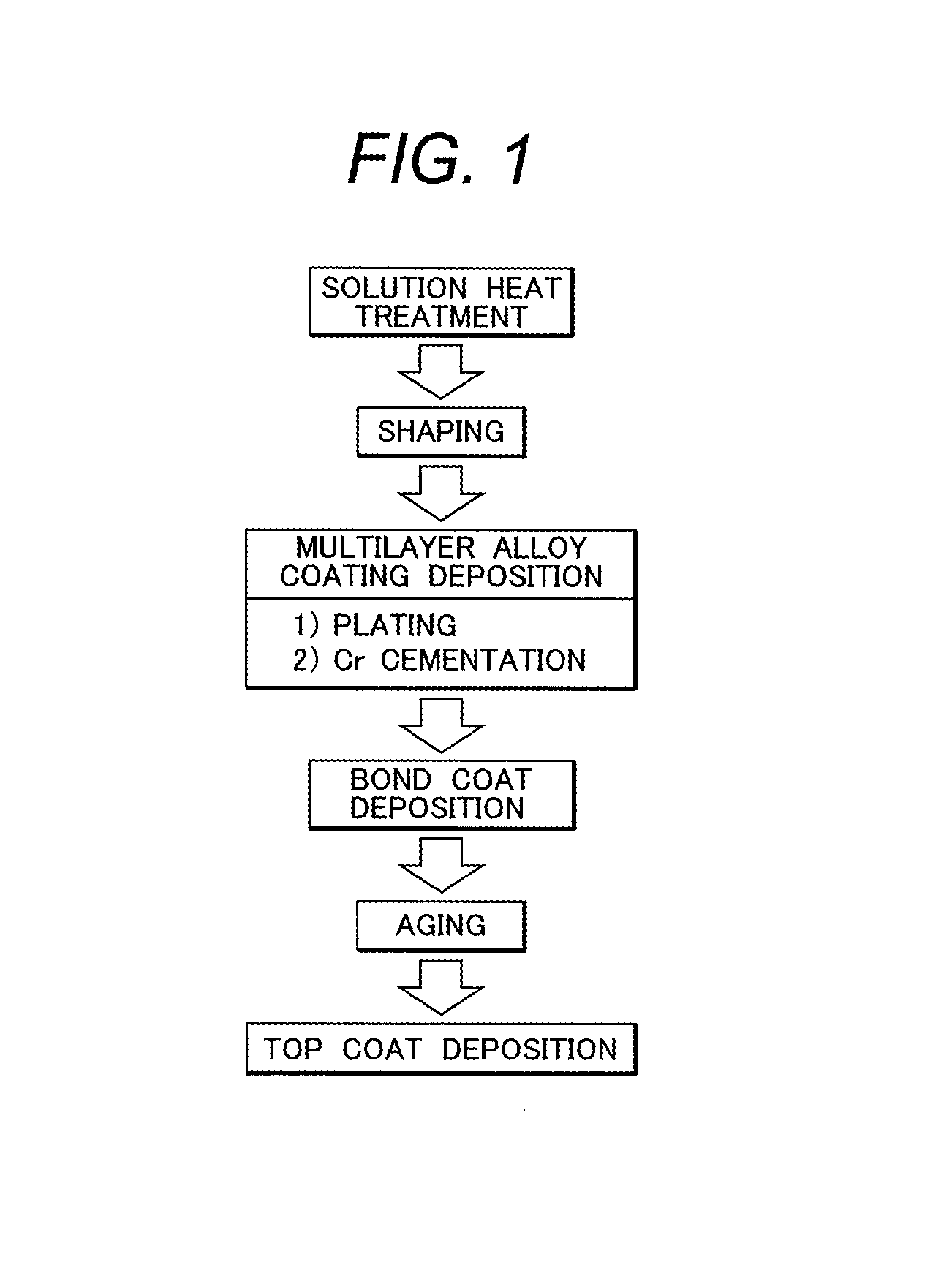
[0061]A single crystal alloy for use in the present invention preferred for a gas turbine member was cast into a rod shape, and was subjected to a solution heat treatment in a vacuum atmosphere under the following multi-stage heating conditions.

1,250° C.·4h→1,260° C.·4h→·1,270° C.·4h→1,280° C.·4h

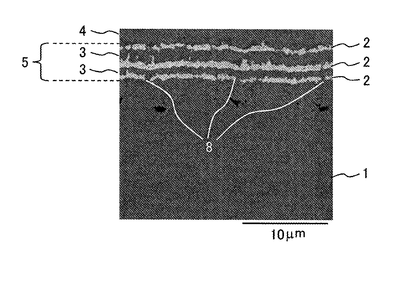
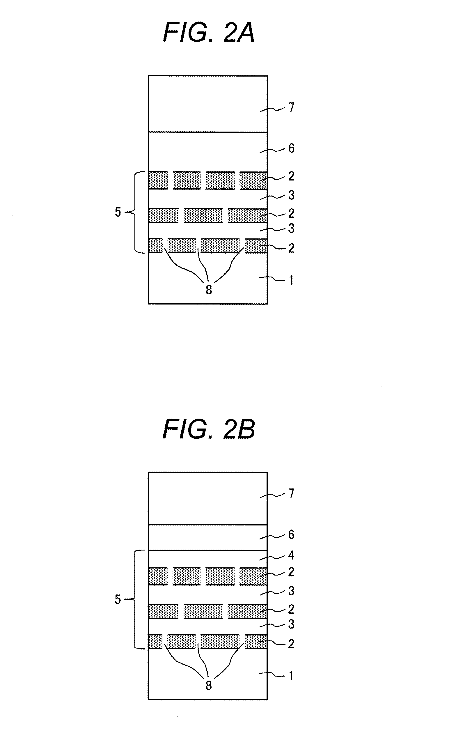
[0062]The rod-shaped casting material after the solution heat treatment was processed into a test piece (diameter 1 inch; thickness 3 mm) to obtain a substrate. In this example, the barrier deposition was performed by using plating, and thus the surface was pretreated by being wet polished with a #600 wet abrasive paper, and degreased with acetone.

[0063]The multilayer plating film was deposited on the washed substrate surface in the following order.

[0064](1) Ni plating: thickness, 2 microns

[0065](2) Re—Ni plating: thickness, 2 microns

[0066](3) Ni—W plating: thickness, 2 microns

[0067](4) Re—Ni plating: thickness, 2 microns

[0068](5) Ni—W plating: thickness, 2 microns

[0069](6) Re—Ni plating: th...

example 2

[0090]A turbine blade for industrial gas turbine formed of the single crystal alloy for use in the present invention used in Example 1 was coated with the coating of Example 1 to obtain a turbine blade for industrial gas turbine. The coating was formed on the blade surface exposed to combustion gas.

[0091]FIG. 7A schematically shows the industrial gas turbine that uses the turbine blade for industrial gas turbine of the example.

[0092]As shown in the figure, the gas turbine is configured from an air intake portion 17, a compressor 18, a combustor 19, a turbine section 20 (including blades and nozzles), and an exhaust unit 21.

[0093]FIG. 7B is a magnified cross sectional view of portion A of FIG. 7A, illustrating details of the turbine section 20 that includes blades and nozzles.

[0094]As shown in the figure, the turbine section is configured from a turbine rotor 11, a shroud 12, a combustor 13, a gas path 14, nozzles 15, and blades 16.

[0095]The turbine blade for industrial gas turbine c...


PUM

PropertyMeasurementUnit
thicknessaaaaaaaaaa
thicknessaaaaaaaaaa
thicknessaaaaaaaaaa

Abstract

Disclosed is a turbine blade for an industrial gas turbine including a blade substrate; a multilayer alloy coating containing a diffusion barrier layer; a bond coat; and a top coat. The blade substrate being formed of a single crystal alloy which consists essentially of 0.06 to 0.08% of C, 0.016 to 0.035% of B, 0.2 to 0.3% of Hf, 6.9 to 7.3% of Cr, 0.7 to 1.0% of Mo, 7.0 to 9.0% of W, 1.2 to 1.6% of Re, 8.5 to 9.5% of Ta, 0.6 to 1.0% of Nb, 4.9 to 5.2% of Al, 0.8 to 1.2% of Co, and the balance being Ni and incidental impurities by weight. The multilayer alloy coating, the bond coat and the top coat being directly and sequentially laminated on a surface of the blade substrate, in which the diffusion barrier layer is a multilayer and a discontinuous layer.

Description

CLAIM OF PRIORITY[0001]The present application claims priority from Japanese Patent application serial No. 2012-154401, filed on Jul. 10, 2012, the content of which is hereby incorporated by reference into this application.BACKGROUND OF THE INVENTION[0002]1. Field of the Invention[0003]The present invention relates to a thermal barrier coating structure preferable for, for example, turbine blades for an industrial gas turbine.[0004]2. Description of Related Art[0005]In gas turbines, there has been an increasing trend for higher combustion gas temperatures for improved efficiency. For materials of turbine blades and nozzles, directional solidification alloys, and single crystal alloys having high heat-resistant temperature have been developed as replacements for common polycrystalline alloys. However, the combustion gas temperature already exceeds the melting points of such blade materials, and it is now common to form a thermal barrier coating (TBC) on substrate surfaces of turbine ...

Claims


Application Information

Patent Timeline
Patent Type & Authority Applications(United States)
IPC IPC(8): F01D5/28
CPCF01D5/288C23C10/00C23C10/02C23C10/38C23C10/60C23C28/00C23C28/321C23C28/3215C23C28/325C23C28/3455C23C28/42F05D2300/10Y02T50/60Y10T428/12618
Inventor IZUMI, TAKESHIARIKAWA, HIDEYUKIKOJIMA, YOSHITAKAMEBATA, AKIRAKASUYA, TADASHINARITA, TOSHIO
Owner HOKKAIDO UNIVERSITY
Why Eureka
Try Eureka