Symmetrical inductively coupled plasma source with symmetrical flow chamber

a plasma source and flow chamber technology, applied in the field of plasma processing reactor chambers, can solve the problems of insufficient approach and difficult to achieve uniformity

Inactive Publication Date: 2014-01-23
APPLIED MATERIALS INC
View PDF12 Cites 15 Cited by
  • Summary
  • Abstract
  • Description
  • Claims
  • Application Information

AI Technical Summary

Problems solved by technology

Such uniformity is becoming more difficult to achieve, as substrate size is increasing and device geometry is shrinking.
As workpiece diameter and chamber

Method used


Image

  • Symmetrical inductively coupled plasma source with symmetrical flow chamber
  • Symmetrical inductively coupled plasma source with symmetrical flow chamber
  • Symmetrical inductively coupled plasma source with symmetrical flow chamber

Examples


Embodiment Construction

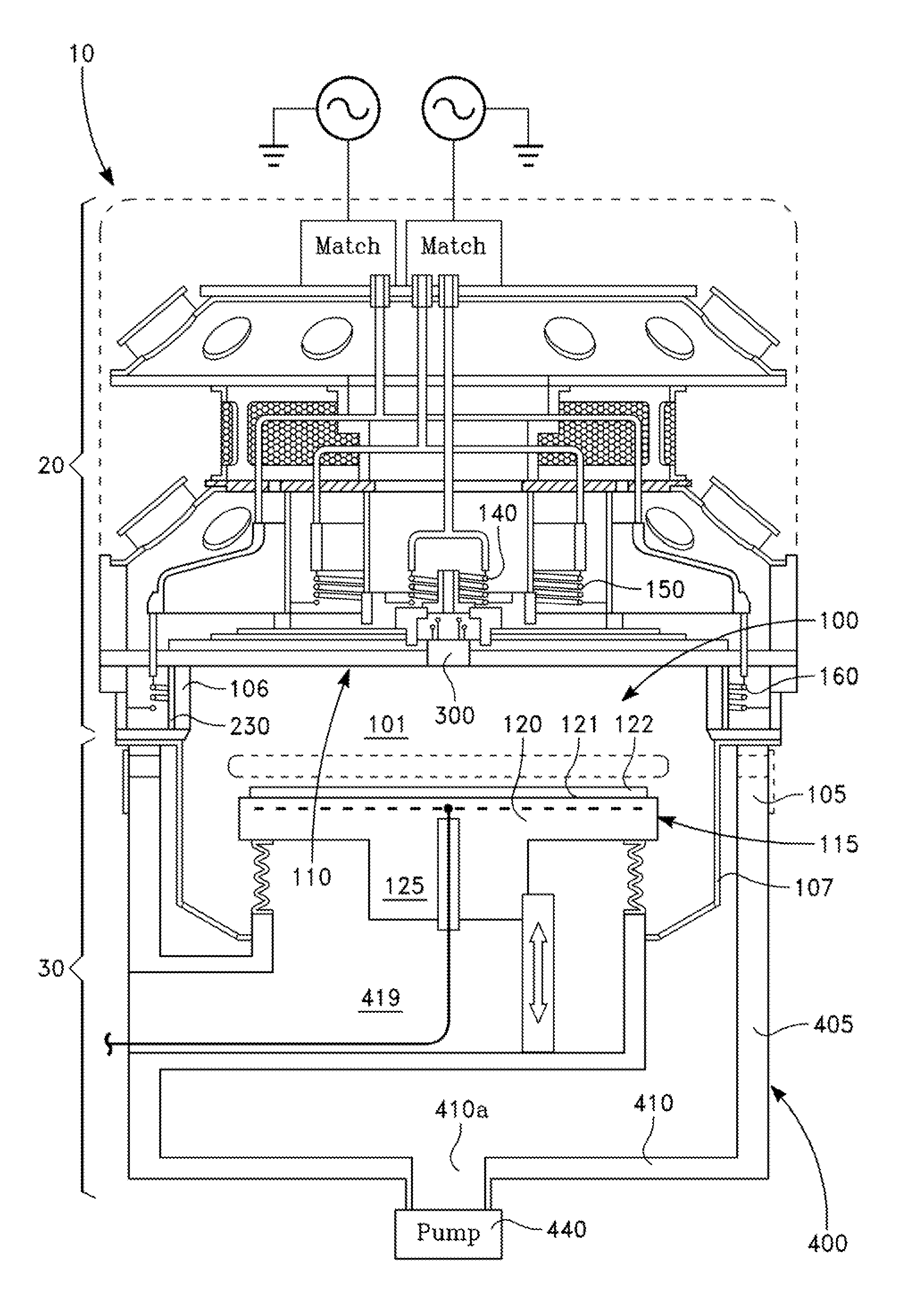
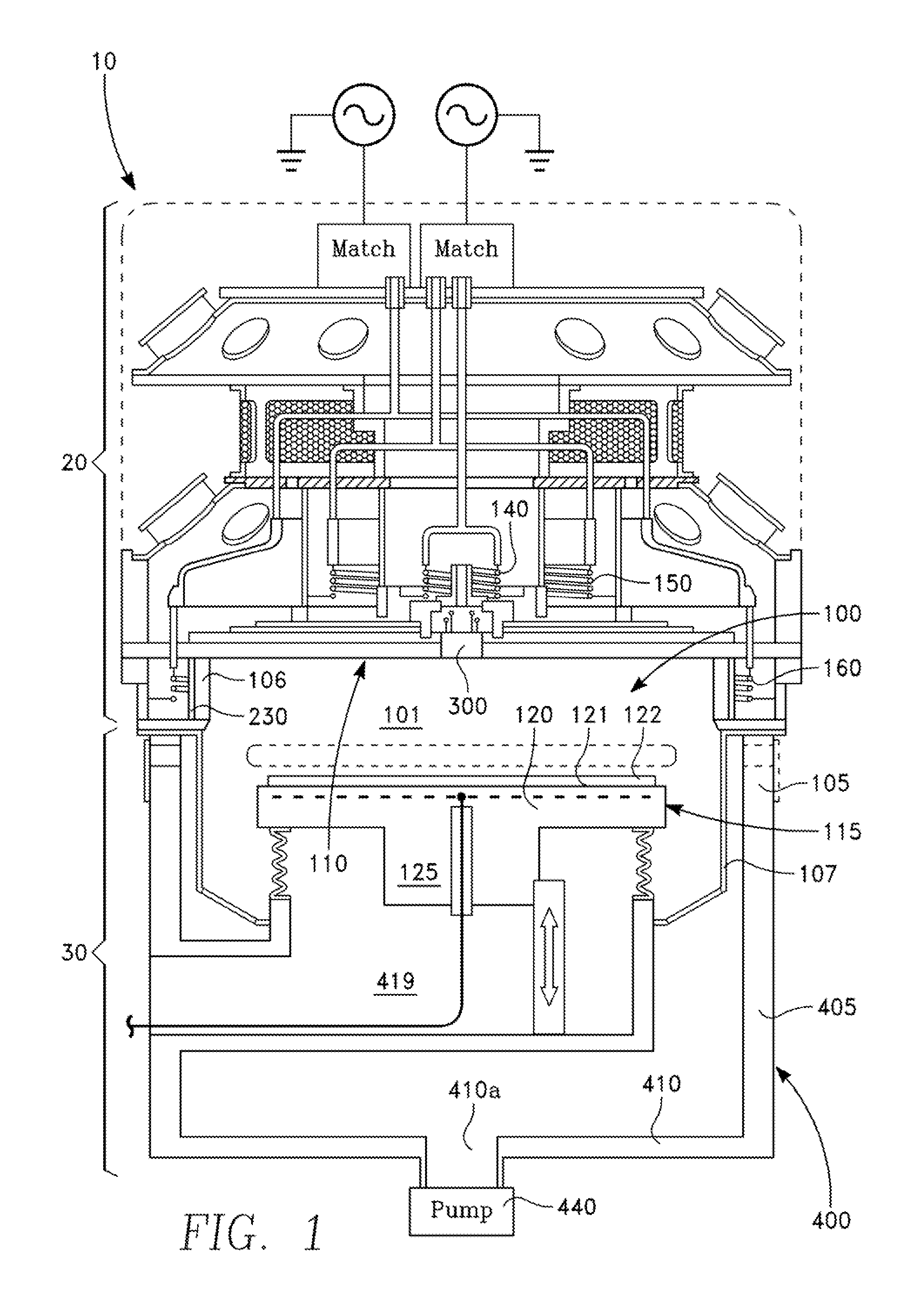
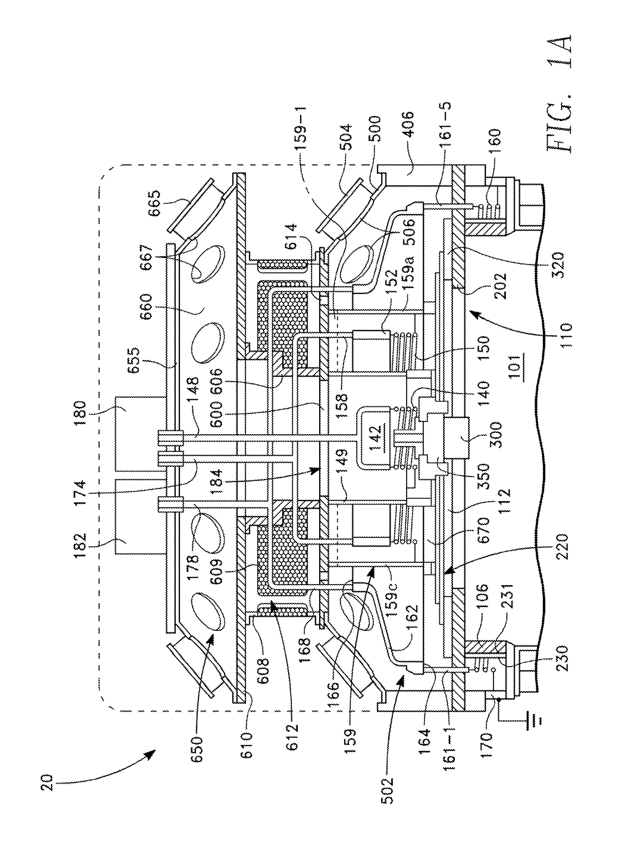
[0040]A plasma reactor 10 depicted in FIG. 1 includes an upper portion 20 depicted in the enlarged view of FIG. 1A and a lower portion 30 depicted in the enlarged view of FIG. 1B. Referring to FIGS. 1, 1A and 1B, the plasma reactor 10 includes a plasma processing chamber 100 having a side wall 105 and a lid assembly 110. The side wall 105 has an axially symmetrical shape, such as a cylinder. The side wall 105 includes an axially symmetrical (e.g., cylindrical) dielectric side window 106 and a chamber liner 107, which may be formed of metal. A workpiece support 115 inside the chamber 100 includes a pedestal 120 having a workpiece support surface 121 facing the lid assembly 110 for holding a workpiece 122, and a post 125 supporting the pedestal 120. A processing region 101 of the chamber 100 is confined by the lid assembly 110, the pedestal 120 and the side wall 105. The pedestal 120 may include an insulated internal electrode 130. Optionally, an electrostatic chucking (ESC) voltage a...


PUM

PropertyMeasurementUnit
Electrical conductoraaaaaaaaaa
Symmetryaaaaaaaaaa

Abstract

A plasma reactor has an overhead multiple coil inductive plasma source with symmetric RF feeds and a symmetrical chamber exhaust with plural struts through the exhaust region providing access to a confined workplace support. A grid may be included for masking spatial effects of the struts from the processing region.

Description

CROSS-REFERENCE TO RELATED APPLICATION[0001]This application claims the benefit of U.S. Provisional Application Ser. No. 61 / 673,937, filed Jul. 20, 2012 entitled SYMMETRICAL MULTIPLE COAXIAL ICP SOURCE AND SYMMETRICAL FLOW CHAMBER, by Andrew Nguyen, et al.BACKGROUND[0002]1. Field[0003]Embodiments of the present invention are generally concerned with a plasma processing reactor chamber for processing workplaces, in which plasma is generated by inductive coupling of RF power to process gases inside the chamber.[0004]2. Description of the Related Art[0005]Electronic devices such as integrated circuits, flat panel displays and the like, are fabricated by a series of processes, in which thin film layers are deposited on substrates and etched into desired patterns. The process steps may include plasma-enhanced reactive ion etching (RIE), plasma-enhanced chemical vapor deposition (CVD), plasma-enhanced physical vapor deposition (PVD).[0006]Uniform distribution of etch rate or deposition ra...

Claims


Application Information

Patent Timeline
IPC IPC(8): C23F1/08C23C14/28
CPCC23F1/08C23C14/28H01J37/3211H01J37/32733H01J37/32834H01J37/321B01J12/002H05H1/46H01J37/3244
Inventor NGUYEN, ANDREWCOLLINS, KENNETH S.RAMASWAMY, KARTIKRAUF, SHAHIDCARDUCCI, JAMES D.BUCHBERGER, JR., DOUGLAS A.AGRAWAL, ANKURKENNEY, JASON A.DORF, LEONIDBALAKRISHNA, AJITFOVELL, RICHARD
Owner APPLIED MATERIALS INC
Why Eureka
Try Eureka