Method for manufacturing metallic glass nanowire, metallic glass nanowire manufactured thereby, and catalyst containing metallic glass nanowire

a technology of metallic glass nanowires and nanowires, which is applied in the direction of metal/metal-oxide/metal-hydroxide catalysts, chemical/physical processes, metal-working apparatuses, etc., can solve the problems of difficult length extension, limited commercial examples of successful commercialization of nanotechnology, and inability to meet the requirements of high-temperature processing, etc., to achieve the effect of small diameter, simple fashion and large quantities

Inactive Publication Date: 2014-02-13
TOHOKU UNIV
View PDF5 Cites 28 Cited by
  • Summary
  • Abstract
  • Description
  • Claims
  • Application Information

AI Technical Summary

Benefits of technology

[0034]According to the present invention, by gas atomization in a supercooled state, of melted metallic glass or a master alloy thereof, metallic glass nanowires of very small diameter can be manufactured in simple fashion and in large quantities. Moreover, by adjusting the gas pressure during gas atomization, metallic glass nanowires having a fibrous state of entwinement of ...

Problems solved by technology

Nanotechnology research, dubbed “nanotech,” has attained a measure of general name recognition, but examples of successful instances of commercialization of nanotech on a commercial scale are extremely limited.
This is due to the complex production techniques needed to design nanostructures, and to the extreme difficulty in handling them due to their microscopic nanosize.
With monocrystal silicon nanowires, which have the highest potential application as transistor elements, length extension remains difficult, and this limitation, which is a problem common to crystalline n...

Method used


Image

  • Method for manufacturing metallic glass nanowire, metallic glass nanowire manufactured thereby, and catalyst containing metallic glass nanowire
  • Method for manufacturing metallic glass nanowire, metallic glass nanowire manufactured thereby, and catalyst containing metallic glass nanowire
  • Method for manufacturing metallic glass nanowire, metallic glass nanowire manufactured thereby, and catalyst containing metallic glass nanowire

Examples


example 1

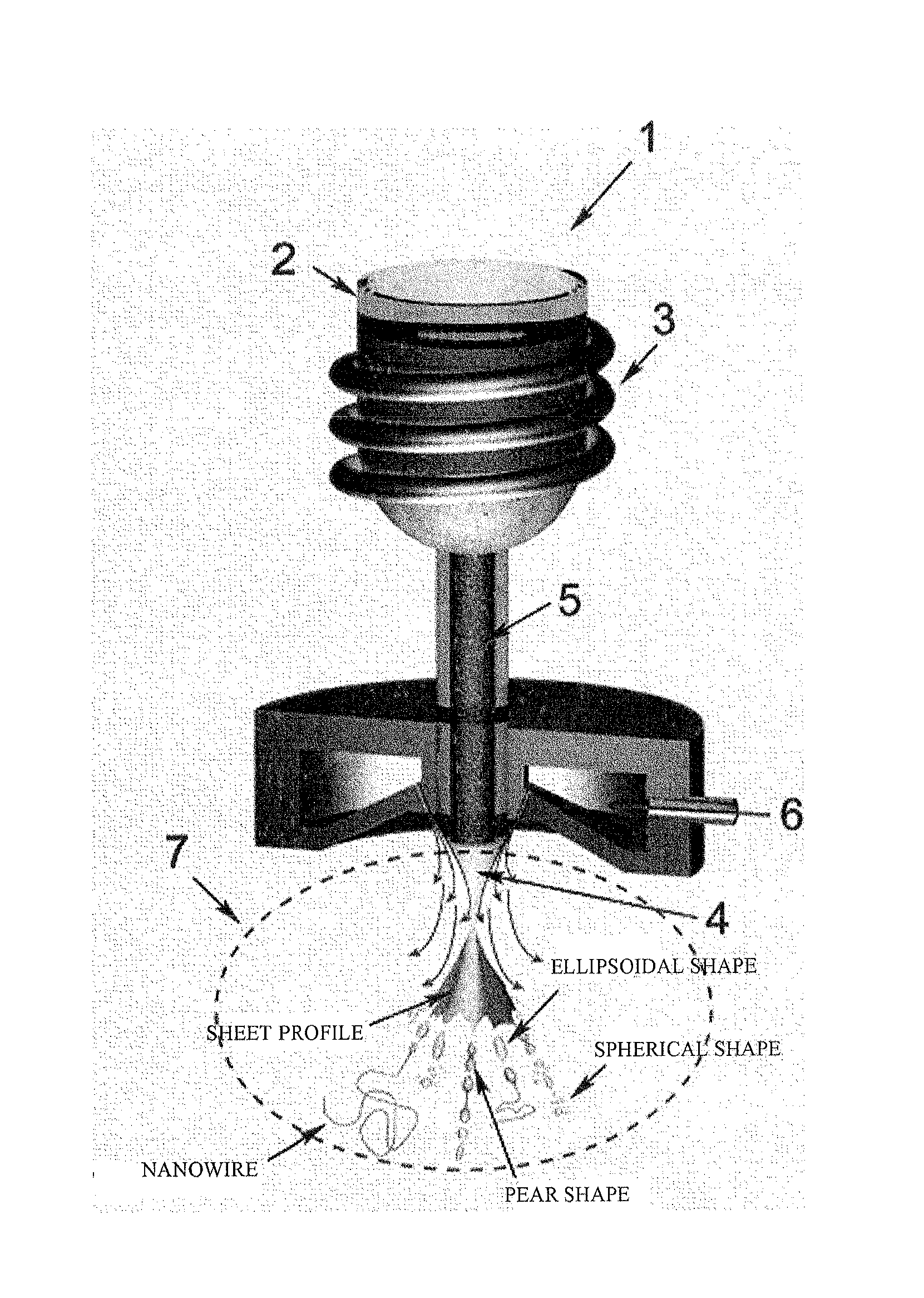
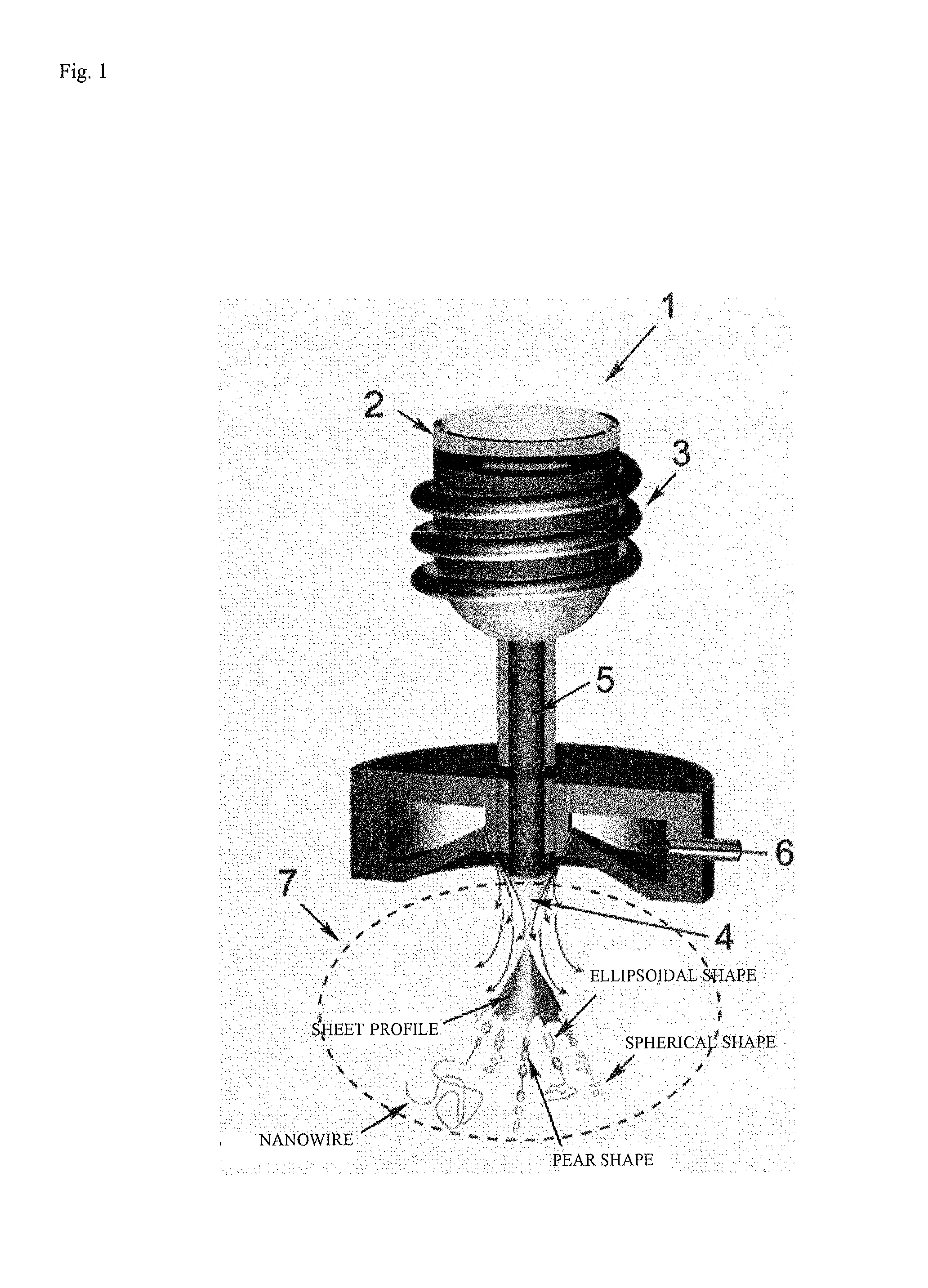
[0099]40 g of metallic glass having the composition Fe76Si9.6B8.4P6 prepared as described above in (Preparation of Fe-based metallic glass) was placed in the crucible 2 of a gas atomization device (made by Makabe R&D Co. Ltd.: compact gas atomization device VF-RQP-100), bringing the melt to 1300 K with the induction heating coil 3. The molten flow 5 was sprayed out at 0.3 kgf / cm2 through the spray port 4 in the bottom of the crucible 2, employing high-pressure argon gas at 18 kgf / cm2 in the gas diffusion zone 7 to spray it until no more melt was left in the crucible 2. FIG. 3 is a scanning electron microscopy (SEM) photo of metallic glass nanowires obtained in Example 1. It was verified that metallic glass nanowires had formed, together with spherical particles, thin fragments of irregular shape, and metallic glass particles of ellipsoidal shape. The average number density of metallic glass nanowires which formed was 1.9 per mm2, and the particle mean diameter of the spherical metal...

example 2

[0100]Gas atomization of metallic glass was carried out in the same manner as in Example 1, except for setting the gas pressure to 42 kgf / cm2. The average number density of metallic glass nanowires which formed was 7.2 per mm2, and the particle mean diameter of the spherical metallic glass particles was 7.1 μm.

example 3

[0101]Gas atomization of metallic glass was carried out in the same manner as in Example 1, except for setting the gas pressure to 70 kgf / cm2. The average number density of metallic glass nanowires which formed was 20.5 per mm2, and the particle mean diameter of the spherical metallic glass particles was 5.1 μm.


PUM

PropertyMeasurementUnit
Pressureaaaaaaaaaa
Pressureaaaaaaaaaa
Metallic bondaaaaaaaaaa

Abstract

Provided is a method for easily manufacturing large volumes of a metallic glass nanowire with an extremely small diameter. This metallic glass nanowire manufacturing method is characterized in that a melted metallic glass or a master alloy thereof is gas-atomized in a supercooled state.

Description

TECHNICAL FIELD[0001]The present invention relates to a method for manufacturing metallic glass nanowire, a metallic glass nanowire manufactured thereby, and a catalyst containing metallic glass nanowire.BACKGROUND ART[0002]Research into catalytic reactions has a long history stretching as far back as ammonia synthesis (a nitrogen fixation method) at the beginning of the 20th century. In the present day, catalysts are employed in a wide range of applications, such as synthesis of feedstocks for chemical products such as daily living products and the like, and of pharmaceuticals, food products, pesticides and fertilizers, and the like. Catalysts also play a role in reducing carbon dioxide emissions from factories and exhaust gases from automobiles, and there are high expectations that catalysts may provide possible solutions to serious environmental problems of global scale, such as the problems of global warming and acid rain.[0003]A catalytic reaction proceeds on the surface of a s...

Claims


Application Information

Patent Timeline
IPC IPC(8): B01J27/185B01J23/755
CPCB01J23/755B01J27/1853C22C45/00C22C45/02C22C45/04C22C45/10B22F9/002B22F9/082B22F2999/00B01J21/066B01J35/06C22C1/0433C22C1/0458C22C1/0466C22C33/02B82Y30/00B01J23/42B01J23/44C22C1/03C22C28/00C22C33/003C22C38/002C22C45/003B22F1/0547C22C1/11B22F2202/03B22F9/08B01J27/185B01J35/02
Inventor NAKAYAMA, KOJIYOKOYAMA, YOSHIHIKO
Owner TOHOKU UNIV
Why Eureka
Try Eureka