Gas Turbine, Gas Turbine Blade, and Manufacturing Method of Gas Turbine Blade

a manufacturing method and technology of gas turbine blade, which are applied in the direction of marine propulsion, vessel construction,foundry moulding apparatus, etc., can solve the problems of reducing the yield rate, blades may become inferior goods, and reduce the thermal efficiency of gas turbines, so as to achieve excellent cooling performance and productivity.

Active Publication Date: 2014-02-27
MITSUBISHI POWER LTD
View PDF6 Cites 9 Cited by
  • Summary
  • Abstract
  • Description
  • Claims
  • Application Information

AI Technical Summary

Benefits of technology

[0020]According to the present invention, a gas turbine and a gas turbine blade having both excellent cooling performance and productivity can be p

Problems solved by technology

Therefore, it becomes a factor of a reduction in the thermal efficiency of the gas turbine.
If some cores are cracked or distorted, or are shifted inside the blade form frame, depending

Method used


Image

  • Gas Turbine, Gas Turbine Blade, and Manufacturing Method of Gas Turbine Blade
  • Gas Turbine, Gas Turbine Blade, and Manufacturing Method of Gas Turbine Blade
  • Gas Turbine, Gas Turbine Blade, and Manufacturing Method of Gas Turbine Blade

Examples


first embodiment

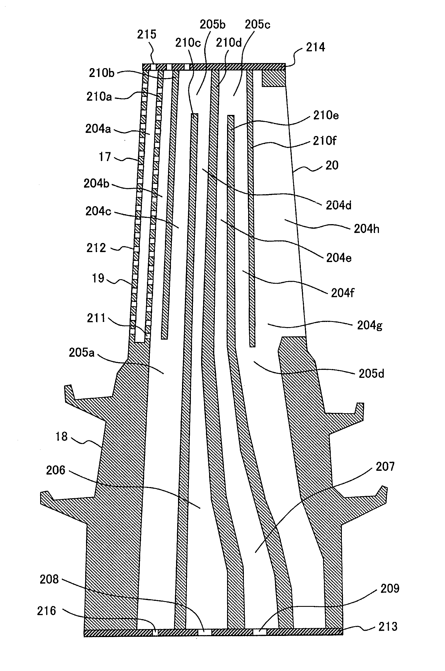
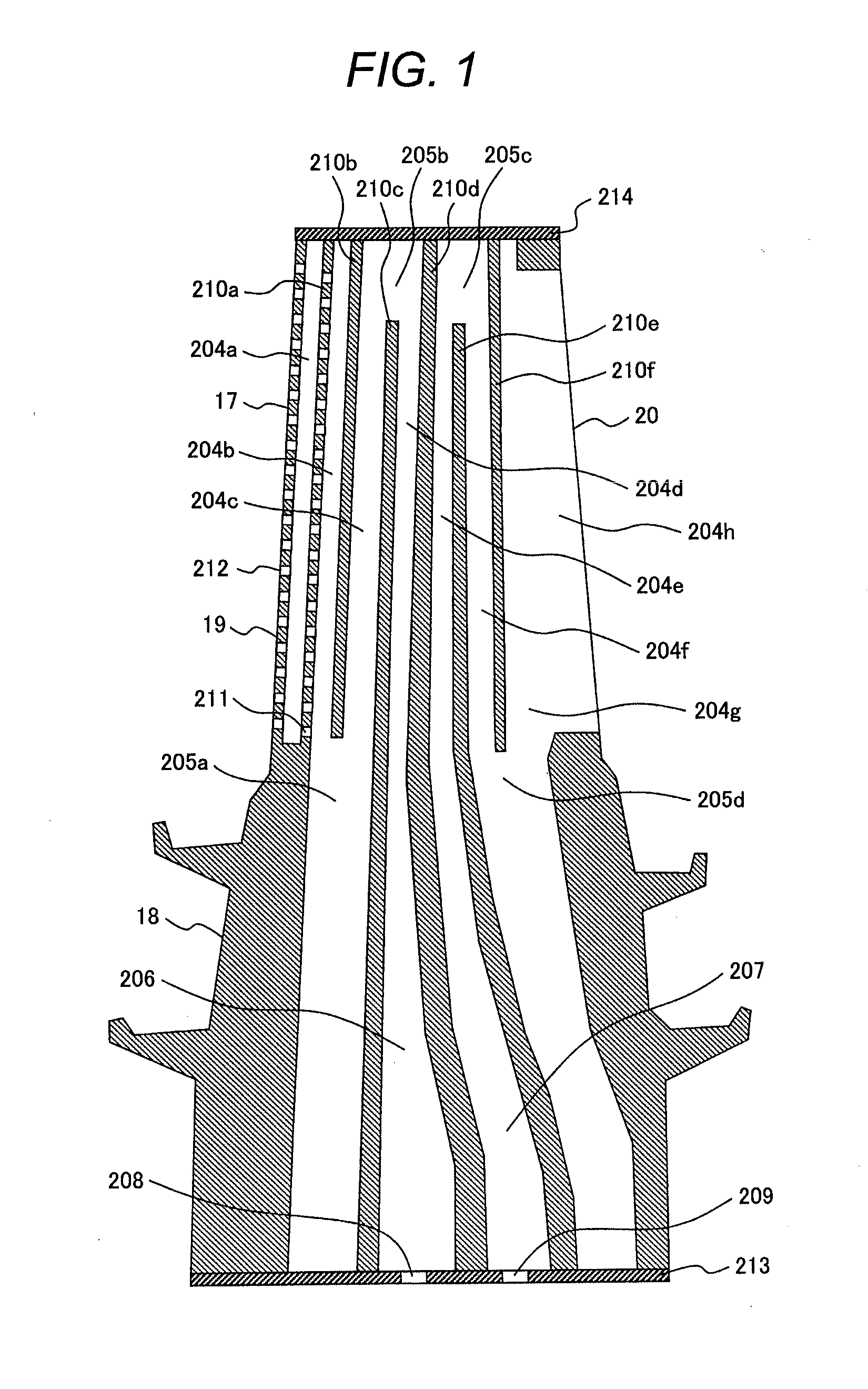
[0037]In this embodiment, the gas turbine blade combined with both excellent cooling performance and productivity will be explained. FIG. 1 shows an embodiment of the cross sectional view of the first stage blade 2 of the gas turbine 101 of the first embodiment in the radial direction.

[0038]In the FIG. 1, the first stage blade 2 includes a blade form portion 17 and a shank portion 18. The blade form portion 17 is composed of a leading edge 19 on the upstream side in the flow direction of the combustion gas which is an working fluid, a trailing edge 20 on the downstream side, and the turbine blade pressure surface in the concave external form and the turbine blade suction surface in the convex external form installed between the leading edge 19 and the trailing edge 20. The shank portion 18 is positioned on the inner peripheral side of the gas turbine from the blade form portion 17 and supports the blade form portion 17.

[0039]The inside of the first stage blade 2 is hollow and a cool...

second embodiment

[0059]In this embodiment, an embodiment of a gas turbine and gas turbine blade will be explained where in addition to the characteristics of the first embodiment, the cooling air flow rate of the turbine blade can be adjusted easily, the adjustment range is wide, and the cost is low.

[0060]FIG. 6 is a cross-sectional view of the first stage blade 2 of the second embodiment in the radial direction. In the drawing, among the turbine blade shown in FIG. 1, the inner peripheral side plate 213 and the outer peripheral side plate 214 are provided with an orifice 215, 216, respectively. The other constitutions have the constitutions with the same reference numerals and the same functions as shown in the first embodiment in FIG. 1, which are explained already, so the explanation of them will be omitted.

[0061]For example, for the turbine blade, after finishing the general processing, the cooling air flow rate test may be executed as a 100% text or a sample test. In the flow rate test, for exa...

third embodiment

[0067]In this embodiment, an embodiment of a gas turbine and a gas turbine blade will be explained where in addition to the characteristics of the first and second embodiments, the cooling air flow rate of the turbine blade can be adjusted easily and the adjustment range is wide.

[0068]FIG. 7 is a cross-sectional view of the turbine blade 101 of the third embodiment in the radial direction. In the drawing, among the turbine blade shown in FIG. 1, a cut portion 217 is formed in the upper part of the partition 210a and a fluid interconnection portion other than the impingement hole 211 is installed. The other constitutions have the constitutions with the same reference numerals and the same functions as shown in the first embodiment in FIG. 1, which are explained already, so the explanation of them will be omitted.

[0069]Here, the structure of injecting cooling air via a small hole such as the impingement hole 211 is large in flow rate change due to hole diameter, so that if the dimensi...


PUM

PropertyMeasurementUnit
Pressureaaaaaaaaaa
Flow rateaaaaaaaaaa
Areaaaaaaaaaaa

Abstract

A gas turbine blade includes a hollow-blade-form portion formed by a leading edge on an upstream side of an working fluid of a gas turbine in a flow direction, a trailing edge on a downstream side of the working fluid in the flow direction, and a suction surface and a pressure surface reaching the trailing edge from the leading edge, and a shank portion for supporting the blade form portion. The blade also includes a partition for connecting the suction surface and the pressure surface in a hollow region of the blade-form portion, coolant paths formed by the partition, the suction surface, and the pressure surface, an impingement cooling hole formed in the partition for dividing the first path that is a flow path nearest to the leading edge side among the coolant paths and the second path adjacent to the first path, and first and second converter portions.

Description

CLAIM OF PRIORITY[0001]The present application claims priority from Japanese patent application JP 2012-186046 filed on Aug. 27, 2012, the content of which is hereby incorporated by reference into this application.BACKGROUND OF THE INVENTION[0002]1. Field of the Invention[0003]The present invention relates to a gas turbine, a gas turbine blade and a manufacturing method of gas turbine blade.[0004]2. Description of Related Art[0005]As a background art of this technical field, there is Japanese Laid-open Patent Application No. 2003-322002 (Patent Literature 1). This patent application states: “The refresh path extends through the inner wall in the radial direction, which inner wall is a boundary of the inner portion of the final flow path in the radial direction, and fluid-interconnects to the cooling air source. The refresh path to the leading edge feed flow path is connected to the flow-in entrance flow path of the serpentine cooling passage passing through the base of the blade and...

Claims


Application Information

Patent Timeline
IPC IPC(8): F01D5/18B23P15/04
CPCB23P15/04F01D5/186B22C9/04B22C9/10F01D5/18F01D5/187F05D2230/211Y10T29/49337
Inventor MORISAKI, TETSUROTAGAWA, HISATOYAGI, MANABUHORIUCHI, YASUHIROHIGUCHI, SHINICHI
Owner MITSUBISHI POWER LTD
Why Eureka
Try Eureka