Conductive mesh supported electrode for fuel cell

a fuel cell and conductive mesh technology, applied in the direction of cell components, electrochemical generators, coatings, etc., can solve the problems of increasing the cost of noble metal catalyst materials, increasing the cost of catalyst materials, and affecting the efficiency of catalysts, so as to facilitate reactant and product flow, and improve the utilization of catalytically active materials.

Inactive Publication Date: 2014-03-20
FORD MOTOR CO +1
View PDF16 Cites 10 Cited by
  • Summary
  • Abstract
  • Description
  • Claims
  • Application Information

AI Technical Summary

Benefits of technology

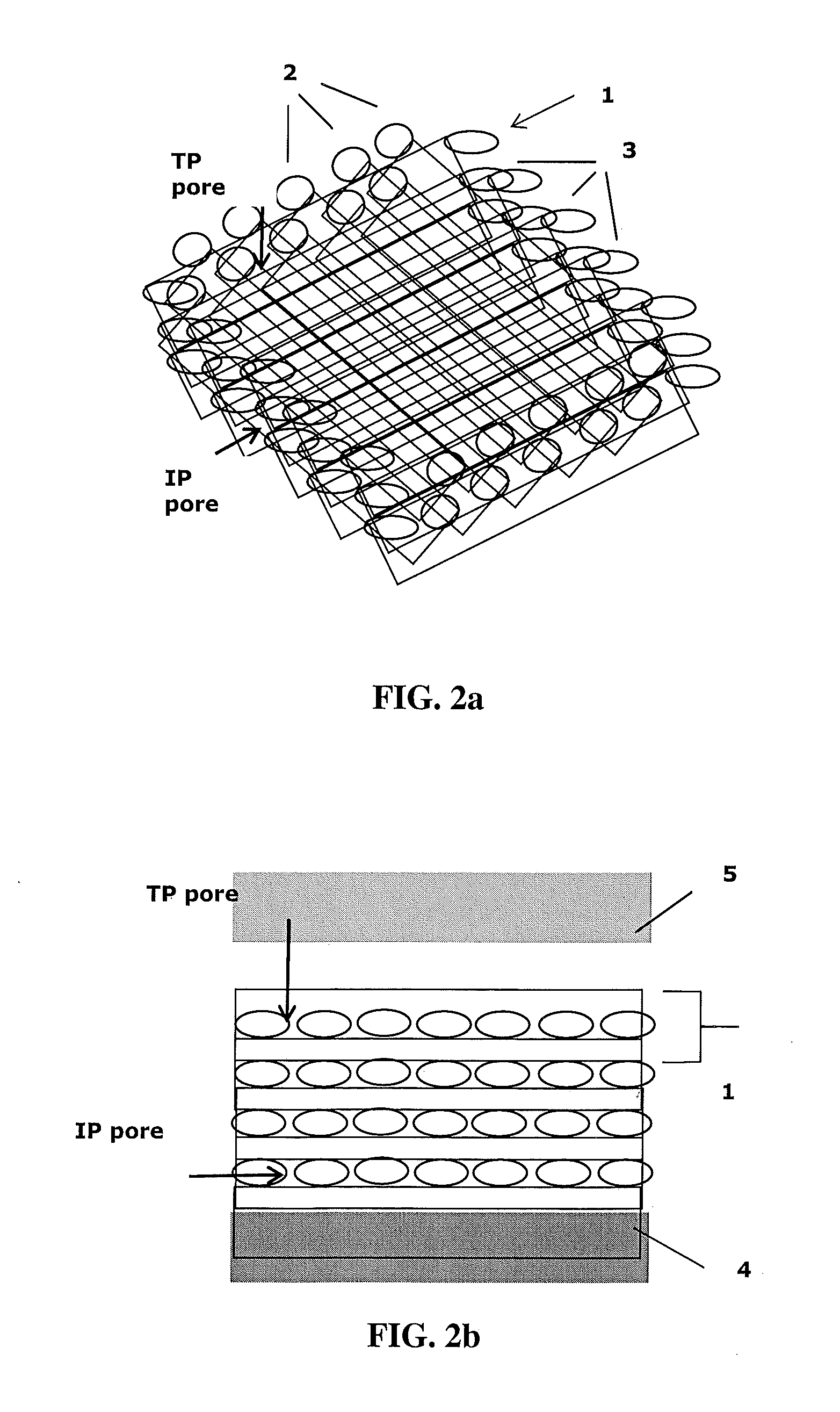
[0011]Use of an appropriate electrically conductive mesh as a catalyst support can provide for improved performance in solid polymer electrolyte fuel cells. The pore size of pores in the mesh should be between about 20 and 3000 nanometers. With appropriate selection of strand geometry in the mesh, suitable electrodes with essentially straight, parallel pores of engineered size can be obtained. A significant improvement in cell voltage at a given current can be expected when such electrodes are used as the cathode.
[0018]The open structure of the mesh based electrodes facilitates reactant and product flow in both the through-plane and in-plane directions of the electrode. Utilization of the catalytically active material can be improved as a result of the close proximity of catalytically active material to the reactant species flow paths. Tortuosities close to 1 can be achieved in principle, and the engineered electrode design allows for a continuous triple phase boundary for the reactants in principle. Further, with appropriate choice of meshes, the electrodes can be mechanically strong, stackable, and corrosion resistant. And from a manufacturing perspective, the properties of fabricated electrodes can be properly controlled by controlling the characteristics of the supporting mesh.

Problems solved by technology

However, noble metal catalyst materials are relatively quite expensive.
This can be quite challenging.
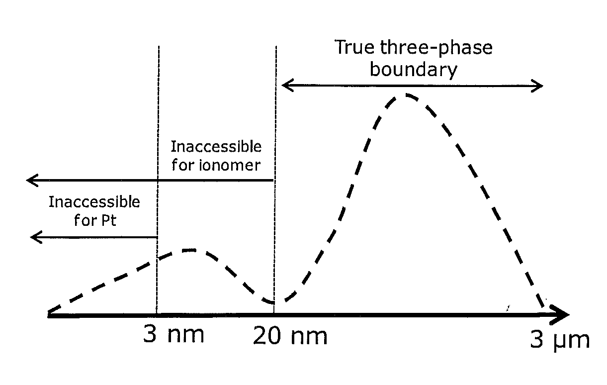
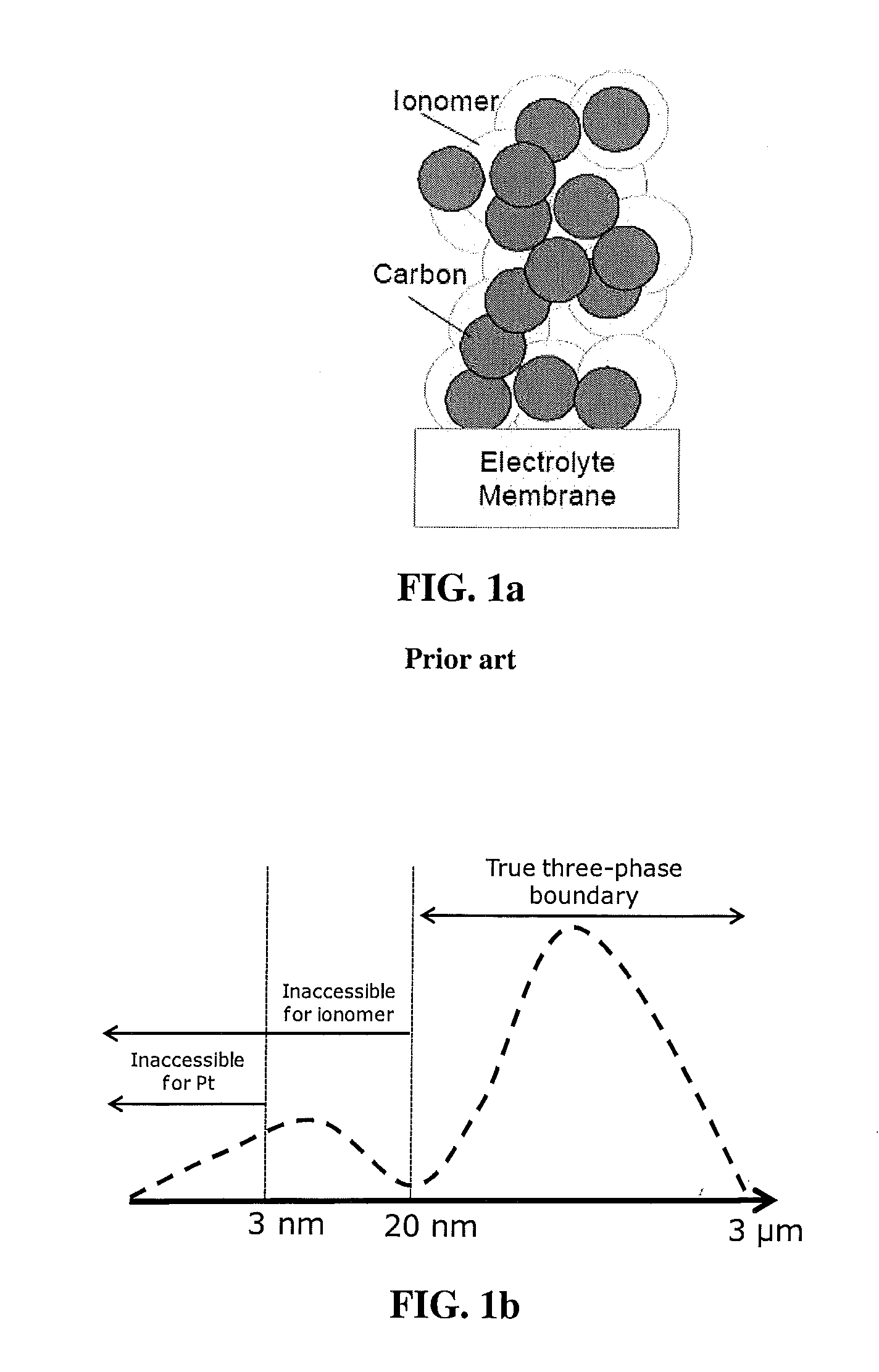
Losses in performance associated with moving the more massive gaseous and liquid species to and from the catalyst via the pores are known as mass transport losses.
Further, the distribution of catalyst and proton conducting ionomer in the electrode is also typically not directly controlled.
As a result, the mass transport characteristics and catalyst utilization in a typical electrode are not as good as they might be in theory.
However, as mentioned above, such electrodes generally exhibit significantly less than ideal catalyst utilization and mass transport characteristics.
Meshes with relatively large open areas were involved, thus resulting in electrodes with relatively large pores.

Method used


Image

  • Conductive mesh supported electrode for fuel cell
  • Conductive mesh supported electrode for fuel cell
  • Conductive mesh supported electrode for fuel cell

Examples


examples

[0050]The potential benefits of using engineered electrodes of the invention as cathodes in otherwise conventional fuel cells were obtained via modeling. In this modeling, conventional solid polymer fuel cell construction was assumed with the exception of certain cathode constructions of the invention. The cathode side of each cell comprised a cathode layer (CL) electrode, a cathode gas diffusion layer (GDL), and a microporous layer (MPL) between these two. The modeling itself was based on the Fuel Cell Simulation Toolbox (FCST), which is a simulation package for solid polymer electrolyte fuel cells. FCST is an open-source code and has an application that allows a user to simulate a cathode electrode. The physical models implemented in FCST are well validated with experimental data from the literature. A detailed description of the model theory, implementation and validation can be found for instance in M. Secanell, Computational modeling and optimization of proton exchange membrane...


PUM

PropertyMeasurementUnit
pore sizeaaaaaaaaaa
diameteraaaaaaaaaa
thickaaaaaaaaaa

Abstract

Electrically conductive meshes with pore sizes between about 20 and 3000 nanometers and with appropriately selected strand geometry can be used as engineered supports in electrodes to provide for improved performance in solid polymer electrolyte fuel cells. Suitable electrode geometries have essentially straight, parallel pores of engineered size. When used as a cathode, such electrodes can be expected to provide a substantial improvement in output voltage at a given current.

Description

BACKGROUND[0001]1. Field of the Invention[0002]The present invention pertains to solid polymer electrolyte fuel cells, and particularly to improved engineered supports for the electrodes therein.[0003]2. Description of the Related Art[0004]Solid polymer electrolyte fuel cells electrochemically convert reactants, namely fuel (such as hydrogen) and oxidant (such as oxygen or air), to generate electric power. These cells generally employ a proton conducting polymer membrane electrolyte between two electrodes, namely a cathode and an anode. A structure comprising a proton conducting polymer membrane sandwiched between two electrodes is known as a membrane electrode assembly (MEA). MEAs in which the electrodes have been coated onto the membrane electrolyte to form a unitary structure are commercially available and are known as a catalyst coated membrane (CCM). In a typical fuel cell, flow field plates comprising numerous fluid distribution channels for the reactants are provided on eithe...

Claims


Application Information

Patent Timeline
Patent Type & Authority Applications(United States)
IPC IPC(8): H01M4/86
CPCH01M4/8605H01M4/8807H01M8/0234H01M2008/1095Y02E60/50
Inventor SOBOLEVA, TATYANAJANKOVIC, JASNAHUSSAIN, MOHAMMEDHU, JINGWEIPUTZ, ANDREAS
Owner FORD MOTOR CO
Why Eureka
Try Eureka