Treatment method for a hydrocarbon-containing system using a biocide

Active Publication Date: 2014-03-20
ENERGY SOLUTIONS (US) LLC
View PDF10 Cites 23 Cited by
  • Summary
  • Abstract
  • Description
  • Claims
  • Application Information

AI Technical Summary

Benefits of technology

[0047]Additional benefits of the invention are that the system may be treated at a lower cost and in a simpler procedure that does not require accurate timing of “shots” of treatment.
[0048]It is also believed that biofilm can act as a diffusion barrier to “shot” dosed biocide, reducing both the contact time and concentration of the biocide or other microbes with the bacteria

Problems solved by technology

Biological contamination is a costly and undesirable phenomenon that can occur in hydrocarbon-containing systems such as oil and gas reservoirs.
Therefore biological contamination of such reservoirs can easily become a problem.
Biological contamination can result in various detrimental effects from the presence of active microbes, such as bacteria, in the hydrocarbon-containing reservoirs.
These detrimental effects include biofouling, corrosion, and biological souring.
The activity of sulfate-reducing prokaryotes (SRP) within hydrocarbon-containing reservoirs is known to cause significant problems for the industry.
This is due to metabolic H2S production leading to problems such as souring and corrosion of pipelines and production facilities.
Once established, the microbes can multiply and spread throughout the reservoir resulting in a potentially rapid rise in hydrogen sulphide production.
In addition, other microbes are known to be problematic.
Additionally, some strains of methanogenic species (e.g. Methanosarcinales species) can produce H2S in their metabol

Method used


Image

  • Treatment method for a hydrocarbon-containing system using a biocide
  • Treatment method for a hydrocarbon-containing system using a biocide
  • Treatment method for a hydrocarbon-containing system using a biocide

Examples


examples

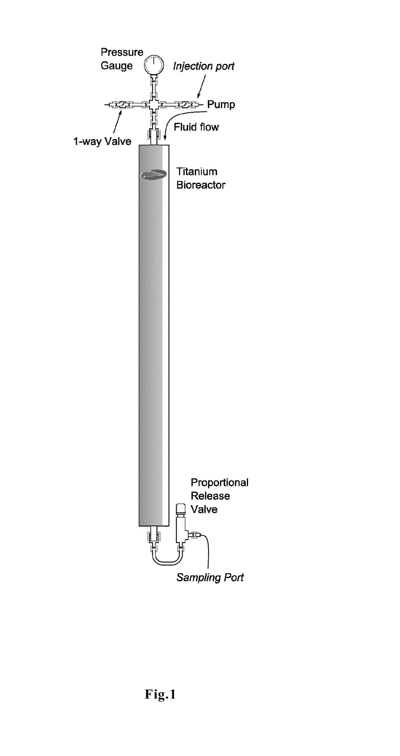
[0166]1.1 Bioreactor Construction

[0167]The bioreactor used was constructed from titanium; this construction eliminated the risk of any production of iron sulphides through corrosion, which in turn would react with injected THPS. The column was 75 cm in length, and had an internal diameter of 5.22 cm. The column was packed with low-iron sand (Fisher, UK) with a glass fibre plug at the base to prevent the draining of sand during filling. The column fittings (injection and production pipework) were constructed from 316 stainless steel (Swagelok).

[0168]A schematic diagram of the bioreactor is given in FIG. 1.

[0169]1.2 Operation (Injection Fluids, Cycle)

[0170]The column was maintained at 1000 psig (70 barg) and 24° C.±1° C. The pressure was held between the pump head and the proportional release valve. The use of 1-way valves in the injection head permitted disconnection and maintenance of the pump without depressurisation of the column.

[0171]The pump used was a high-pressure liquid chro...


PUM

PropertyMeasurementUnit
Fractionaaaaaaaaaa
Fractionaaaaaaaaaa
Timeaaaaaaaaaa

Abstract

A method for reducing the effects of biological contamination in a hydrocarbon-containing system comprising the steps of continuously adding a formulation comprising tris(hydroxymethyl)phosphine or a tetrakis(hydroxymethyl)phosphonium salt to the system for one day or more; monitoring the efficacy of the continuous treatment by an assessment of the extent to which there is any effect on the environment that is attributable to metabolic activity of active microbes present in the system; wherein the tris(hydroxymethyl)phosphine or tetrakis(hydroxymethyl)phosphonium salt is added at a concentration of from 1 to 30 ppm based on the total volume of aqueous fluid added to the system, and wherein the formulation is added to the system at a stage to minimize incompatibility with any other chemicals that are added to the aqueous fluid. The treatment disrupts the microbial activity of active microbes in the hydrocarbon-containing system and can prevent or reduce detrimental effects arising from the presence of active microbes in the system.

Description

CROSS-REFERENCE TO RELATED APPLICATIONS[0001]This application is a U.S. national stage entry under 35 U.S.C. §371 of International Application No. PCT / GB2012 / 050456 filed Feb. 29, 2012, which claims priority to UK Application No. 1103748.8 filed on Mar. 7, 2011, the whole content of this application being herein incorporated by reference for all purposes.TECHNICAL FIELD OF THE INVENTION[0002]The present invention relates to the treatment of hydrocarbon-containing systems, such as oil and gas reservoirs, using a method that disrupts microbial activity, e.g. it may disrupt bacterial activity. The method therefore prevents or reduces the detrimental effects from the presence of active microbes, such as bacteria.BACKGROUND OF THE INVENTION[0003]Biological contamination is a costly and undesirable phenomenon that can occur in hydrocarbon-containing systems such as oil and gas reservoirs.[0004]To increase the yield from hydrocarbon-containing reservoirs, water is pumped under pressure int...

Claims


Application Information

Patent Timeline
IPC IPC(8): A01N57/20
CPCA01N57/20C02F1/50C02F5/00C02F2103/10C09K8/54C09K8/58C09K8/605C09K2208/20A01N57/34C10G29/20
Inventor JONES, CHRISEDMUNDS, STEPHANIECOLLINS, GARETH
Owner ENERGY SOLUTIONS (US) LLC
Why Eureka
Try Eureka