Energy storage device with heating device and method for heating energy cells of an energy storage device

a technology of energy storage device and heating device, which is applied in the direction of battery/fuel cell control arrangement, secondary cell servicing/maintenance, electrochemical generator, etc., can solve the problems of power reduction in the entire energy supply line, failure of the entire system, so as to reduce the energy and time demands, avoid heating up, and low internal resistance

Active Publication Date: 2014-04-10
ROBERT BOSCH GMBH
View PDF2 Cites 4 Cited by
  • Summary
  • Abstract
  • Description
  • Claims
  • Application Information

AI Technical Summary

Benefits of technology

[0012]One concept of the present invention is to reduce the energy and time demands for warming energy cells of energy storage devices in order to precondition the energy cells, by using an energy storage device with individually connectable energy storage modules, in which only a subset of the available energy cells are preheated. The energy necessary for this is now only a fraction of the energy required to warm the entire energy storage device. Similarly, only a relatively small period of time is necessary for warming the subset of the energy cells. The preheated energy cells can then be advantageously used for initial energy supply by means of the energy storage device, for example during a starting-up process of an electric vehicle driven using the energy storage device.
[0013]A further concept of the present invention is to identify a subset of the energy cells of an energy storage device as dedicated energy cells for an initial energy supply, for example during a starting-up process of an electric vehicle driven using the energy storage device. The dedicated subset of the energy cells can then preferably have battery cells which have a particularly low internal resistance at low temperatures in order to be able to avoid heating-up, or at least to minimize the energy and time demands when heating this subset of the energy cells.

Problems solved by technology

The series circuit comprising a plurality of battery modules is associated with the problem that the entire line fails when a single battery module fails.
Such a failure of the energy supply line can result in failure of the entire system.
Furthermore, temporarily or permanently occurring power reductions of an individual battery module can result in power reductions in the entire energy supply line.
At low temperatures, the internal resistance is increased and so the full power cannot be taken from the battery under certain circumstances.
The heating-up process in this case is energy-intensive and time-consuming.

Method used


Image

  • Energy storage device with heating device and method for heating energy cells of an energy storage device
  • Energy storage device with heating device and method for heating energy cells of an energy storage device

Examples


Embodiment Construction

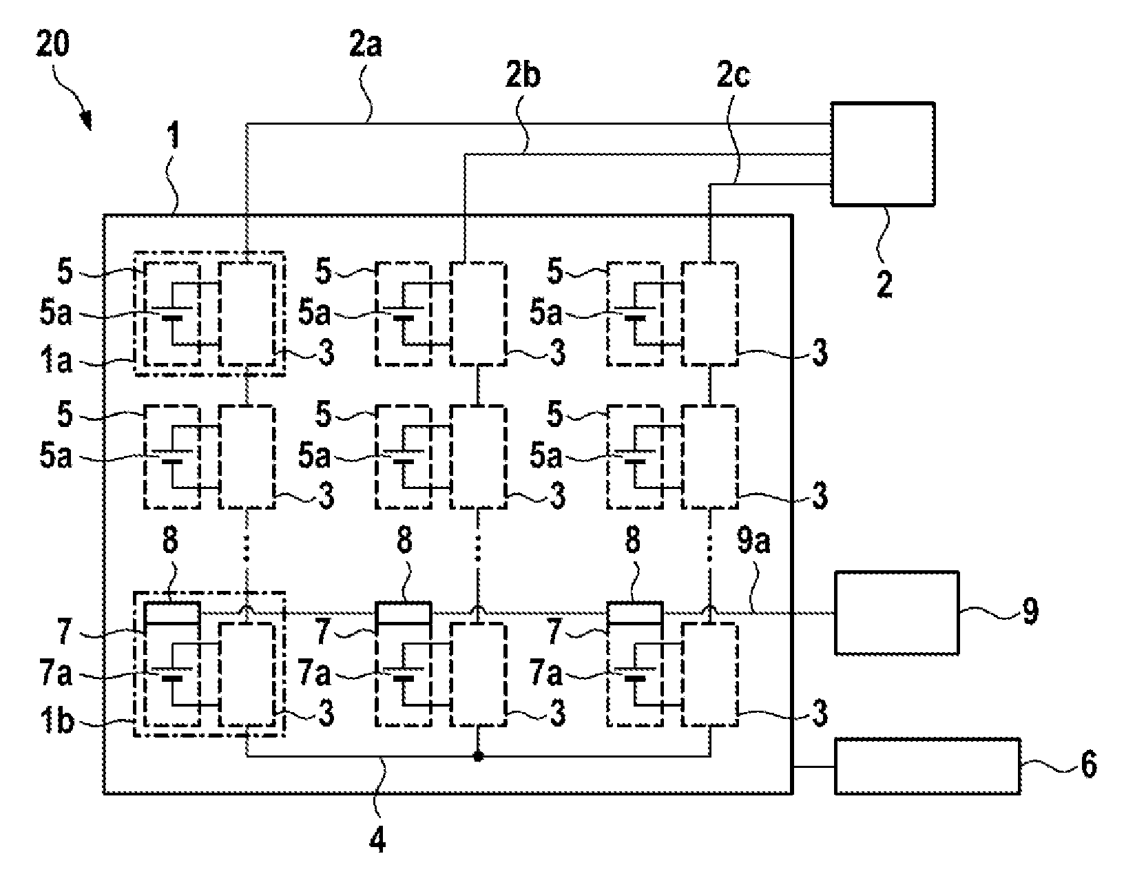
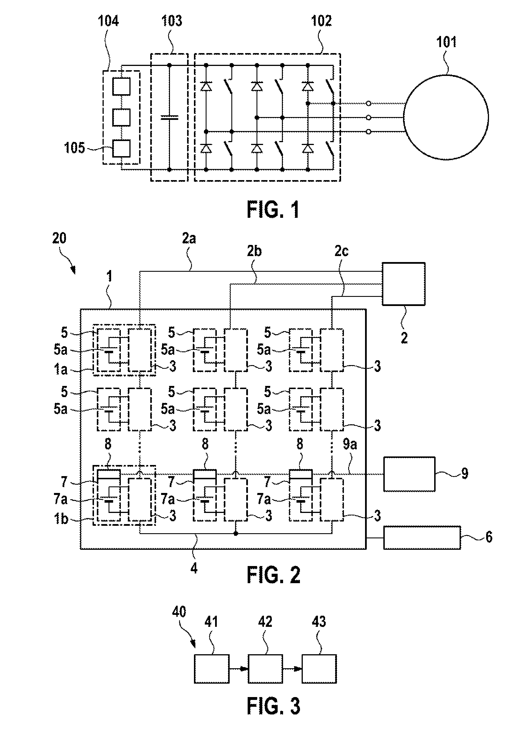
[0019]FIG. 2 shows a system 20 for voltage conversion of DC voltage supplied by means of energy storage modules 1a, 1b into an n-phase AC voltage. The system 20 comprises an energy storage device 1 having energy storage modules 1a, 1b, which are connected in series in energy supply branches. By way of example, three energy supply branches are shown in FIG. 2, which energy supply branches are suitable for generating a three-phase AC voltage, for example for a three-phase machine 2. In principle, however, any other number of phases n is likewise possible. The energy storage device 1 has a phase connection at each energy supply branch, which phase connections can be connected in each case to phase conductors 2a, 2b, 2c and are connected to the phase conductors 2a, 2b, 2c for example for the operation of, for example, an electric machine. By way of example, the system 20 in FIG. 2 is used to feed an electric machine 2, in particular in an electrically driven vehicle. However, it can als...


PUM

PropertyMeasurementUnit
temperatureaaaaaaaaaa
n-phase supply voltageaaaaaaaaaa

Abstract

The invention relates to an energy storage device (1) for generating an n-phase supply voltage for an electric machine (2), wherein n≧1, with n energy supply branches which are connected in parallel and which can each be connected to one of n phase conductors (2a, 2b, 2c), wherein each of the energy supply branches has a large number of energy storage modules (1a, 1b) which are connected in series and which each comprise: an energy storage cell module (5, 7) which has at least one energy storage cell (5a, 7a) and a coupling device (3), which is designed to connect the energy storage cell module (5, 7) selectively into the respective energy supply branch or to bridge said energy storage cell module, wherein in each case at least one of the energy storage modules (1b) also has in each case one heating element (8) for the at least one energy storage cell (7a); and a heating device (9), which is connected to the heating elements (8) and which is designed to actuate the heating elements (8) for heating the energy storage cells (7a) in the groups of energy storage modules (1b).

Description

BACKGROUND OF THE INVENTION[0001]The invention relates to a heating device for an energy storage device, in particular in a battery direct converter circuit for supplying power to electric machines, and to a method for heating energy cells of an energy storage device, in particular when starting an electrically driven vehicle.[0002]The trend is that in the future electronic systems which combine new energy storage technologies with electrical drive technology will be used increasingly both in stationary applications, such as wind power installations or solar installations, and in vehicles, such as hybrid or electric vehicles.[0003]FIG. 1 shows, by way of example, the feeding-in of alternating current into a three-phase electric machine 101. In this case, a DC voltage provided from a DC voltage intermediate circuit 103 is converted into a three-phase AC voltage by a converter in the form of a pulse-controlled inverter 102. The DC voltage intermediate circuit 103 is fed by a line 104 ...

Claims


Application Information

Patent Timeline
Patent Type & Authority Applications(United States)
IPC IPC(8): H01M10/637
CPCH01M10/5026H01M10/425H01M10/441H01M10/486H01M10/0525H01M10/63H01M10/637H01M10/6571H01M10/615B60L58/27B60L58/19Y02E60/10Y02T10/70
Inventor FEUERSTACK, PETERWEISSENBORN, ERIKKESSLER, MARTIN
Owner ROBERT BOSCH GMBH
Why Eureka
Try Eureka