Insulated wire and coil using same

a technology of insulated wire and coil, which is applied in the direction of insulated conductors, cables, conductors, etc., can solve the problems of increasing the risk of partial discharge in the insulated wire of the motor, reducing the space factor of the insulated wire, and suppressing the miniaturization of the motor, so as to reduce the size and weight, improve the dynamic performance, and achieve high power output

Active Publication Date: 2014-04-17
HITACHI METALS LTD
View PDF8 Cites 14 Cited by
  • Summary
  • Abstract
  • Description
  • Claims
  • Application Information

AI Technical Summary

Benefits of technology

[0008]In recent years, the motors used for industrial equipment have been reduced in size and weight. In addition, inverter drive for improving dynamic performance, together with high voltage drive for high power output, is being developed rapidly. Since the motor is driven at high voltage and at the same time is inverter-driven, the overlapping of the high voltage drive with the inverter drive increases the risk of partial discharge occurrence in an insulated wire of the motor. Therefore, higher PDIV is required in an insulating layer of an insulated wire.

Problems solved by technology

Since the motor is driven at high voltage and at the same time is inverter-driven, the overlapping of the high voltage drive with the inverter drive increases the risk of partial discharge occurrence in an insulated wire of the motor.
In case that an insulating layer formed of the polyimide disclosed by JP-A 9-106712 has a thin thickness, it is difficult to achieve a sufficient PDIV level.
However, the use of a thick insulating layer increases a diameter of the insulated wire, thereby decreases a space factor of the insulated wire or suppresses the miniaturization of the motor.

Method used


Image

  • Insulated wire and coil using same
  • Insulated wire and coil using same
  • Insulated wire and coil using same

Examples


embodiments

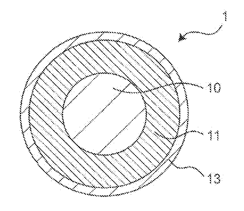
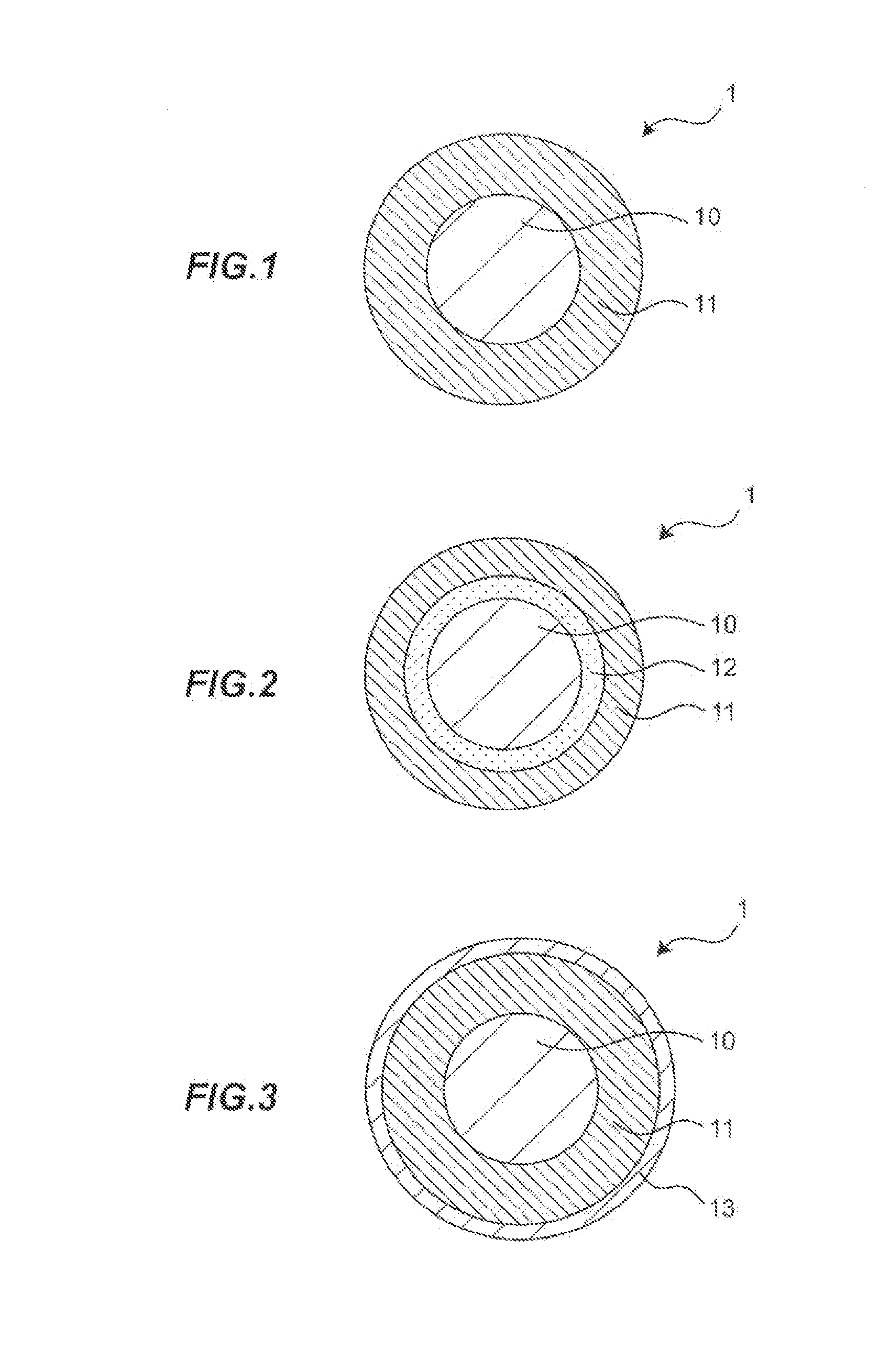
[0026]Next, preferred embodiments according to the invention will be explained below in conjunction with the accompanying drawings.

[0027]Firstly, a polyimide varnish used to form a polyimide resin which constitutes an insulating layer will be explained.

[0028](Polyimide Varnish)

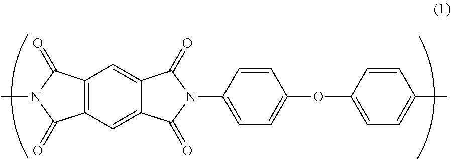
[0029]The polyimide varnish contains polyamic acid. The polyamic acid is synthesized from carboxylic acid and diamine, and contains an amide bond in the molecule. The polyamic acid is polymerized by heating to form the polyimide resin having a predetermined repeating unit.

[0030]In the present embodiment, a polyimide resin comprising a repeating unit A as a part of the molecular structure is formed from a polyimide varnish containing polyamic acid comprising the repeating unit A formed by heating. The polyimide resin exhibits low relative permittivity and high partial discharge inception voltage, since the water absorption coefficient is not greater than 2.8% after 24 hours under the condition at temperature of...

example 1

[0085]For manufacturing an insulated wire, a polyimide varnish used for forming an insulating layer consisting essentially of polyimide resin was prepared by the method as described below.

[0086](Preparation of Polyimide Varnish)

[0087]Firstly, 437.5 g of 4,4′-diaminodiphenyl ether (ODA) as diamine was dissolved in 3697.2 g of N-methyl-2-pyrrolidone (NMP) as solvent. Thereafter, 393.2 g of pyromellitic acid anhydride (PMDA) and 93.6 g of 3,3′,4,4′-biphenyltetracarboxylic dianhydride (s-BPDA) as carboxylic anhydrides were dissolved in NMP as the solvent. Then, by being synthesized with stirring for 12 hours at room temperature in a nitrogen environment, a polyimide varnish containing the polyamic acid A and polyamic acid B was prepared. In order to improve the coating workability of the polyimide varnish, the polyimide varnish was diluted by adding the solvent to the varnish. In Example 1, the polyimide varnish comprising the polyimide resin in which the molar ratio of the repeating un...

examples 2 to 5

[0102]In Examples 2 to 5, as shown in Table 1, polyimide varnishes were prepared by appropriately changing the additive amount of PMDA and s-BPDA as carboxylic anhydrides, to manufacture insulated wires in the same manner as the insulated wire in Example 1.


PUM

PropertyMeasurementUnit
humidityaaaaaaaaaa
temperatureaaaaaaaaaa
water absorption coefficientaaaaaaaaaa

Abstract

An insulated wire includes a conductor and an insulating layer formed on an outer periphery of the conductor, and the insulating layer is composed essentially of a polyimide resin having a repeating unit A represented by Formula (1) as a part of a molecular structure, in which a water absorption coefficient is not greater than 2.8% after 24 hours under condition at temperature of 40° C. and humidity of 95%

Description

[0001]The present application is based on Japanese patent application No. 2012-228586 filed on Oct. 16, 2012, the entire contents of which are incorporated herein by reference.BACKGROUND OF THE INVENTION[0002]1. Field of the Invention[0003]The present invention relates to an insulated wire and a coil using the same, more particularly, to an insulated wire and a coil using the same, to be used in motors and the like.[0004]2. Description of the Related Art[0005]An electrical equipment such as motor typically comprises a coil. A coil in motors is formed with using an insulated wire, and is formed by winding the insulated wire around a core of the motor, or joining the insulated wires together by welding or the like. The insulated wire comprises an insulative coating (insulating layer) on an outer periphery of a conductor. The insulating layer is formed by applying an insulative varnish containing a resin component dissolved in an organic solvent to the conductor, and baking the conduct...

Claims


Application Information

Patent Timeline
Patent Type & Authority Applications(United States)
IPC IPC(8): H01B7/29
CPCH01B7/292H01B3/306Y10T428/294
Inventor USHIWATA, TAKAMIHONDA, YUKINABESHIMA, SHUTAKIKUCHI, HIDEYUKI
Owner HITACHI METALS LTD
Why Eureka
Try Eureka