Aerofoil cooling

a technology of aerofoil and component cooling, which is applied in the direction of liquid fuel engines, marine propulsion, vessel construction, etc., can solve the problems of reduced strength of the vortex, uncooling of the hot turbine components, and cooling air from the compressor used to cool the hot turbine components is not used fully to extract work from the turbine, so as to improve the cooling scheme effect of the aerofoil componen

Active Publication Date: 2014-05-22
ROLLS ROYCE PLC
View PDF5 Cites 29 Cited by
  • Summary
  • Abstract
  • Description
  • Claims
  • Application Information

AI Technical Summary

Benefits of technology

[0019]It would be desirable to further improve the effectiveness of aerofoil component cooling schemes.
[0021]Advantageously, the coolant flow can be confined by the helical passage. This generates a centrifugal force, which can be maintained over the length of the passage, the force driving the coolant outwards and thereby encouraging the flow to remain attached to the walls defining the outer parts of the passage. The force also helps to reduce the thickness of the boundary layer, promoting high levels of heat transfer. In addition, the passage can increase the velocity in the flow, which can improve metal to coolant heat transfer. Also, the helical shape can increase the gas-washed surface area of the passage.
[0025]The chamber can include a core passage which extends along the axis, the helical passage being in fluid communication with the core passage such that coolant flows along the core passage and is then fed into the helical passage. The core passage can thus replenish coolant which may be lost from the helical passage e.g. via film cooling effusions holes. The fluid communication may be arranged such that coolant flows along the core passage and is fed into the helical passage over substantially the entire length of the helical passage. Preferably, the core passage tapers in the direction of coolant flow, such an arrangement can encourage the coolant to be progressively fed from the core passage into the helical passage. The taper can progress smoothly and / or in a series of steps. Preferably, the core passage is configured such that substantially none of the coolant flow exits the core passage other than by the helical passage.
[0031]The helical passage can include heat transfer augmentation features which cause the coolant flow to separate from and reattach to the walls thereof. For example, the features can be at outer wall at the side of the helical passage most distal from the axis, and can take the form of trip strips and / or steps. Such features generally promote secondary swirling flow and thereby increase turbulent mixing.
[0032]The chamber may include one or more further helical passages which each spiral in a plurality of turns around said axis. When the chamber has a plurality of helical passages, the rate of temperature increase with axial distance of the coolant carried by each passage as it flows along the passage can be reduced, allowing the coolant to have an improved cooling effect over greater axial distances.
[0033]The or each helical passage may have an outer wall at the side of the helical passage most distal from the axis, the wall or walls lying on a cylindrical or frustoconical surface which is substantially coaxial with said axis. In particular, a frustoconical surface which tapers with increasing axial distance from an inlet to the chamber, is consistent with a decrease in overall flow area for the chamber with increasing axial distance. In this way, flow velocities in the chamber can be maintained despite e.g. coolant loss to component surface film cooling. Typically, the wall or walls may cover at least 50%, or more preferably at least 80%, of the cylindrical or frustoconical surface, which can increase the gas-washed surface area of the helical passage.

Problems solved by technology

However as turbine entry temperatures increase, the life of an un-cooled turbine falls, necessitating the development of better materials and the introduction of internal air cooling.
The cooling air from the compressor that is used to cool the hot turbine components is not used fully to extract work from the turbine.
Therefore, as extracting coolant flow has an adverse effect on the engine operating efficiency, it is important to use the cooling air effectively.
However, the strength of the vortex reduces as flow is extracted up the span of the aerofoil.

Method used


Image

  • Aerofoil cooling
  • Aerofoil cooling
  • Aerofoil cooling

Examples


Embodiment Construction

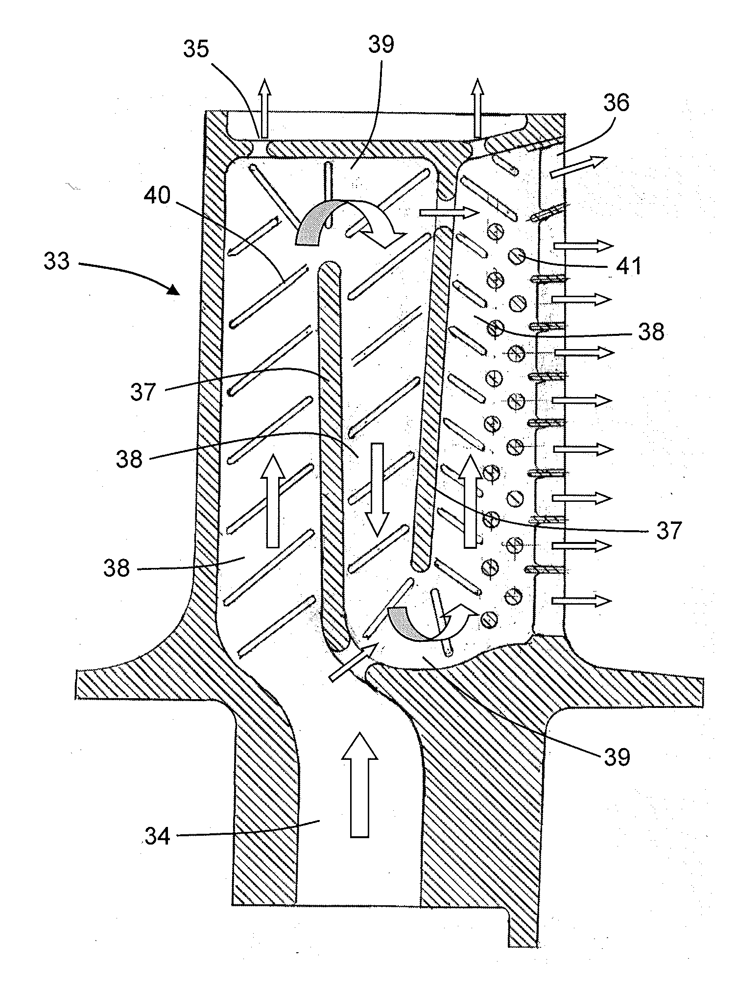
[0053]The present invention relates to a component having an aerofoil portion which contains a helical passage for coolant flow, the passage spiralling around an axis that extends in the length direction of the aerofoil portion. The helical shape can increase the gas-washed surface area of the passage. Further, the cooling flow can be confined to flow in a spiral direction by the walls of the passage.

[0054]The complex shape of the helical passage limits the manufacturing processes that can be employed to produce the component. However, the component can be manufactured using, for example, Virtual Pattern Casting (VPC) or Direct Metal Laser Sintering (DMLS), both being processes used in rapid prototyping procedures.

[0055]In the case of VPC, an energy beam, such as a laser, cures a polymer impregnated ceramic powder in a series of layers to produce an intricately-shaped core. The core is fired and built into a wax pattern die, which is then used to produce wax patterns for use in an i...


PUM


Abstract

An aerofoil component of a gas turbine engine is provided. The component has a longitudinally extending aerofoil portion which spans, in use, a working gas annulus of the engine. The aerofoil portion contains an internal chamber for a flow of coolant. The chamber includes a helical passage which spirals in a plurality of turns around an axis that extends in the length direction of the aerofoil portion.

Description

FIELD OF THE INVENTION[0001]The present invention relates to the cooling of an aerofoil component of a gas turbine engine.BACKGROUND OF THE INVENTION[0002]With reference to FIG. 1, a ducted fan gas turbine engine generally indicated at 10 has a principal and rotational axis X-X. The engine comprises, in axial flow series, an air intake 11, a propulsive fan 12, an intermediate pressure compressor 13, a high-pressure compressor 14, combustion equipment 15, a high-pressure turbine 16, and intermediate pressure turbine 17, a low-pressure turbine 18 and a core engine exhaust nozzle 19. A nacelle 21 generally surrounds the engine 10 and defines the intake 11, a bypass duct 22 and a bypass exhaust nozzle 23.[0003]The gas turbine engine 10 works in a conventional manner so that air entering the intake 11 is accelerated by the fan 12 to produce two air flows: a first air flow A into the intermediate pressure compressor 13 and a second air flow B which passes through the bypass duct 22 to pro...

Claims


Application Information

Patent Timeline
Patent Type & Authority Applications(United States)
IPC IPC(8): F01D5/18
CPCF01D5/187F01D5/186F01D5/188F05D2250/15F05D2250/25
Inventor TIBBOTT, IANJACKSON, DOUGAL RICHARD
Owner ROLLS ROYCE PLC
Why Eureka
Try Eureka