Radio-frequency sputtering system with rotary target for fabricating solar cells

a rotary target and sputtering technology, which is applied in the direction of electrolysis components, vacuum evaporation coatings, coatings, etc., can solve the problems of unstable plasma and deposition process, high cost, and high cost, and achieve the low-damage requirement of high-efficiency solar cells

Active Publication Date: 2014-07-03
TESLA INC
View PDF6 Cites 16 Cited by
  • Summary
  • Abstract
  • Description
  • Claims
  • Application Information

AI Technical Summary

Problems solved by technology

However, currently available sputtering systems for manufacturing PVDs often rely on applying a high direct-current (DC) voltage to the target, and may result in a charge build-up on floating-potential surfaces and arcing.
The occurrence of arcing makes the plasma and the deposition process unstable and therefore unpredictable.
However, DC-pulsed sputtering usually cannot meet the low-damage requirement of high-efficiency solar cells.

Method used


Image

  • Radio-frequency sputtering system with rotary target for fabricating solar cells
  • Radio-frequency sputtering system with rotary target for fabricating solar cells
  • Radio-frequency sputtering system with rotary target for fabricating solar cells

Examples


Embodiment Construction

[0024]The following description is presented to enable any person skilled in the art to make and use the embodiments, and is provided in the context of a particular application and its requirements. Various modifications to the disclosed embodiments will be readily apparent to those skilled in the art, and the general principles defined herein may be applied to other embodiments and applications without departing from the spirit and scope of the present disclosure. Thus, the present invention is not limited to the embodiments shown, but is to be accorded the widest scope consistent with the principles and features disclosed herein.

Overview

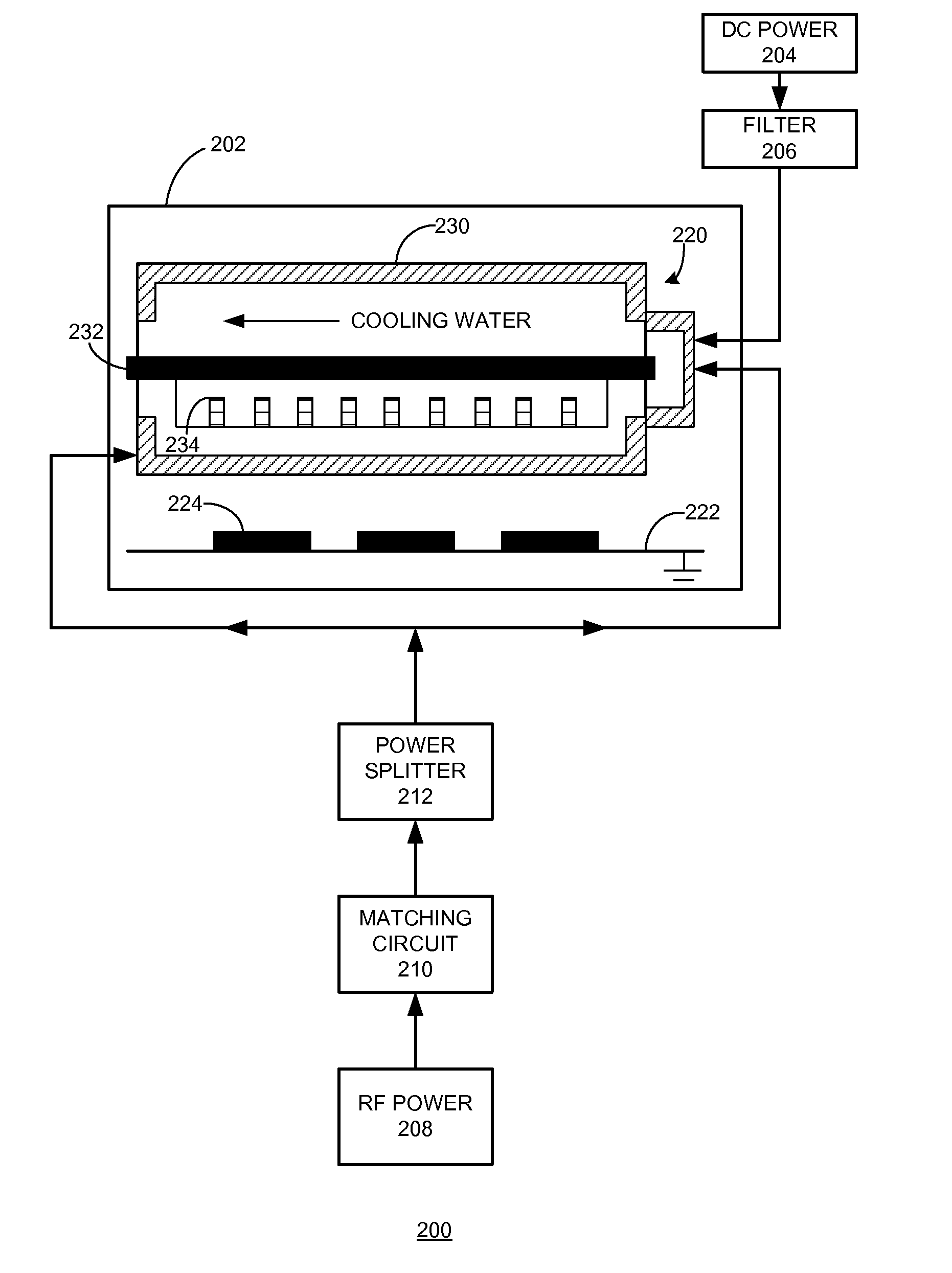
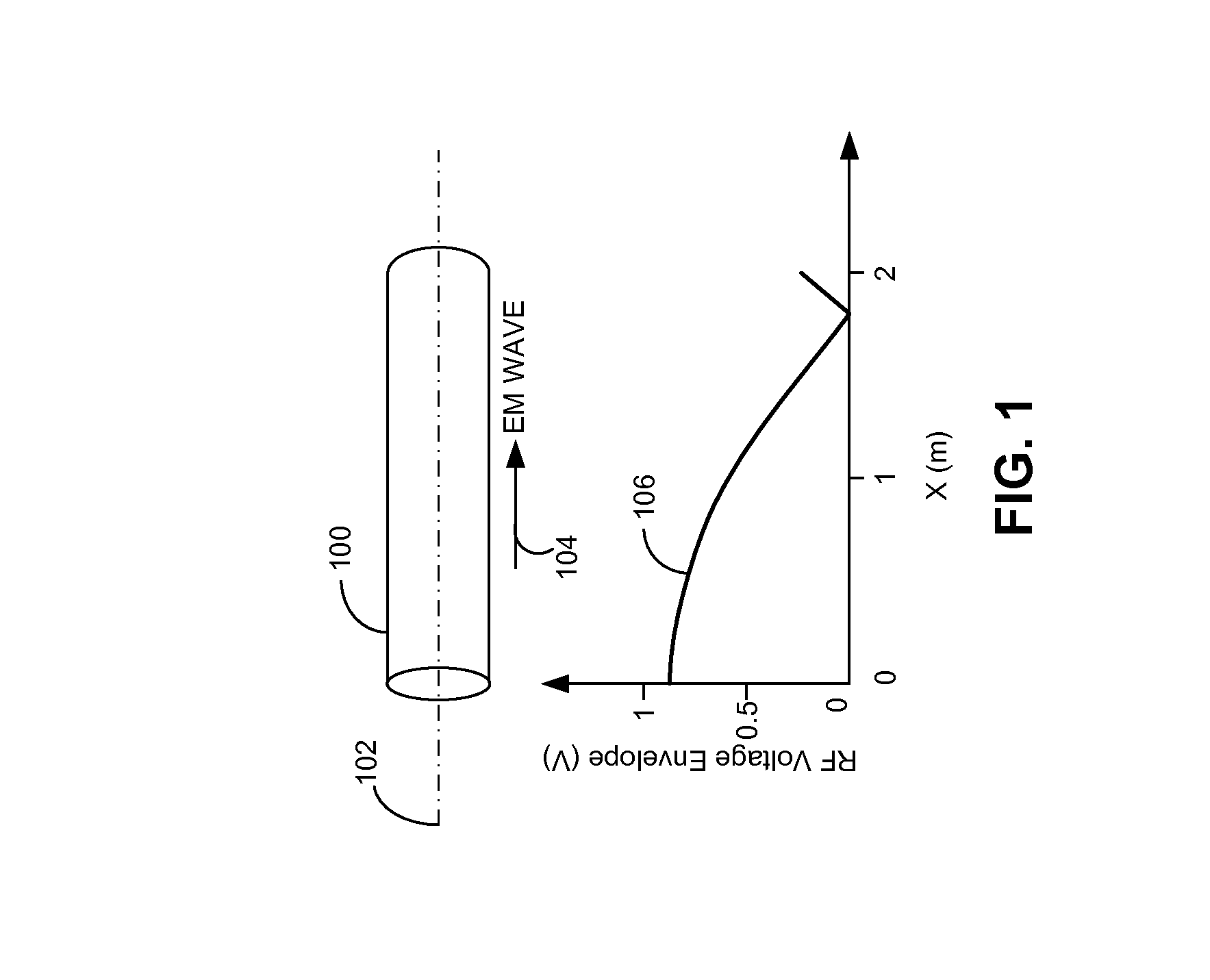
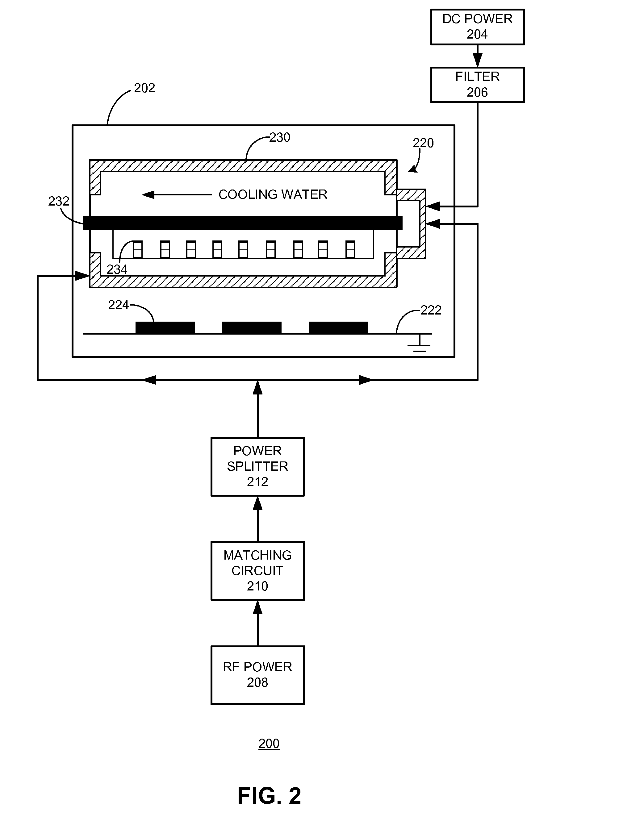
[0025]Embodiments of the present invention provide an RF sputtering system equipped with a rotary target to ensure uniform film deposition and target erosion. To prevent a formation of a standing wave, in some embodiments, the RF power is split 50-50 and each portion is fed to one end of the rotary target. In alternative embodiments, one end of the...


PUM

PropertyMeasurementUnit
lengthaaaaaaaaaa
lengthaaaaaaaaaa
RF frequencyaaaaaaaaaa

Abstract

One embodiment of the present invention provides a sputtering system for large-scale fabrication of solar cells. The sputtering system includes a reaction chamber, a rotary target situated inside the reaction chamber which is capable of rotating about a longitudinal axis, and an RF power source coupled to at least one end of the rotary target to enable RF sputtering. The length of the rotary target is between 0.5 and 5 meters.

Description

RELATED APPLICATION[0001]This application claims the benefit of U.S. Provisional Application No. 61 / 747,081, Attorney Docket Number SSP12-1006PSP, entitled “Applying Radio-Frequency Sputtering to a Rotary Target System,” by inventors Zhigang Xie, Wei Wang, Zheng Xu, and Jianming Fu, filed 28 Dec. 2012.BACKGROUND[0002]1. Field[0003]This disclosure is generally related to a sputtering system used for fabricating solar cells. More specifically, this disclosure is related to a radio frequency (RF) sputtering system equipped with a rotary target.[0004]2. Related Art[0005]Anti-reflection coatings (ARCs) play an important role in ensuring high efficiency of silicon-based solar cells because the bare Si has a high surface reflection rate. Most ARCs include one or more layers of dielectrical material, such as SiO2, SiNx, etc. Moreover, many solar cells also include a thin layer of transparent conducting oxide (TCO) material (such as indium-tin-oxide (ITO) or indium doped zinc oxide (ZIO)), w...

Claims


Application Information

Patent Timeline
Patent Type & Authority Applications(United States)
IPC IPC(8): H01L31/18
CPCH01J37/342H01J37/3444H01J37/3452H01L31/1876H01J37/32082H01J37/3423H01J37/347H01L31/1884H01J37/3405H01J37/3417H01J37/3438H01J37/345C23C14/3407Y02E10/50C23C14/351H01J37/32091H01J37/32137H01J37/3414H01L31/02168
Inventor XIE, ZHIGANGWANG, WEIXU, ZHENGFU, JIANMING
Owner TESLA INC
Why Eureka
Try Eureka