Electrically conductive material, emitter containing electrically conductive material, and method for its manufacture

a technology of electrically conductive materials and emitters, which is applied in the direction of conductors, electrical apparatus casings/cabinets/drawers, and connection devices, etc., can solve the problems of insufficient electrical resistance of the filaments proposed therein, insufficient electrical resistance for the operation of very long emitters at common electrical voltage in industrial applications, and insufficient length of filaments and/or heating rods. , to achieve the effect of reducing the thickness of the fiber bundl

Inactive Publication Date: 2014-07-31
HERAEUS NOBLELIGHT GMBH
View PDF0 Cites 9 Cited by
  • Summary
  • Abstract
  • Description
  • Claims
  • Application Information

AI Technical Summary

Benefits of technology

[0074]Another advantageous embodiment of the method provides that the structure made up of electrically conductive fibers includes fiber bundles that are reduced in thickness before they are introduced into the structure or that the thickness of the fiber bundles in the structure is reduced after production of the structure, or both. Reducing the thickness of the fibers before introducing them into the structure and/or of the structure altogether allows the electrical properties of the electrically conductive material to be varied additionally and particularly effectively. Preferably, the fibers are present in the form of fiber bundles or rovings whose thickness is reduced as specified above. Rovings of reduced thickness have, in particular, an elliptical or rectangular cross-section; they preferable are crushed rovings. Alternatively or in addition, the entire structure can be crushed from electrically conductive fibers, in particular by rolling. The thickness of the fiber bundles of r

Problems solved by technology

However, if extended emitters are to be operated at common voltages, the stretched tapes used as electrically conductive material prove to be too thin, too brittle and too fissure-prone.
However, the electrical resistance of the filaments proposed therein is insufficient for operation of very long emitters at common electrical voltages in industrial applications.
Moreover, the length of the filaments and/or heating rods is strongly limited.
Moreover, the low mechanical stability of the filaments renders industrial processing difficult, if not impossible.
However, this method necessitates a laborious third heat treatment, in which each filament needs to be treated separately.
Moreover, doping with carbides produces a very brittle, electrically conductive material, which is not suitable for use in large emitters.
However, since the high temperatures used for graphitization lower the resistance of the electrically conductive material, the effect is counter-productive in the manufacture of electrically conductive material for long emitters, since electrically conductive materials having high resistance at high filament temperatures are needed for lon

Method used


Image

  • Electrically conductive material, emitter containing electrically conductive material, and method for its manufacture
  • Electrically conductive material, emitter containing electrically conductive material, and method for its manufacture
  • Electrically conductive material, emitter containing electrically conductive material, and method for its manufacture

Examples


exemplary embodiment 1

[0123]Exemplary embodiment 1 relates to the manufacture of a filament according to FIG. 1. Unidirectional thermoplastic carbon fiber tape 8 is used for this purpose, from which the tape-shaped filaments 6 are cut to the needed dimensions (length and width), wherein the length of the filament 6 exceeds its width by far. In this context, the carbon fibers 4 extend in the direction of longitudinal extension 10 of the filament 6, parallel to the cutting edge 11. Subsequently, electrical contacts (not shown) are attached to the filaments 6, the filaments 6 are carbonized, and then graphitized according to need.

[0124]The filaments 6 are then provided with bore holes 13 of a diameter of 0.1 mm to 1.5 mm introduced into the material by a laser. The bore holes 13 are arranged appropriately in this context, such that each individual carbon fiber 4 is severed at least once between the two electrical contacts (not shown here). This ensures that the current cannot directly follow along the indiv...

exemplary embodiment 2

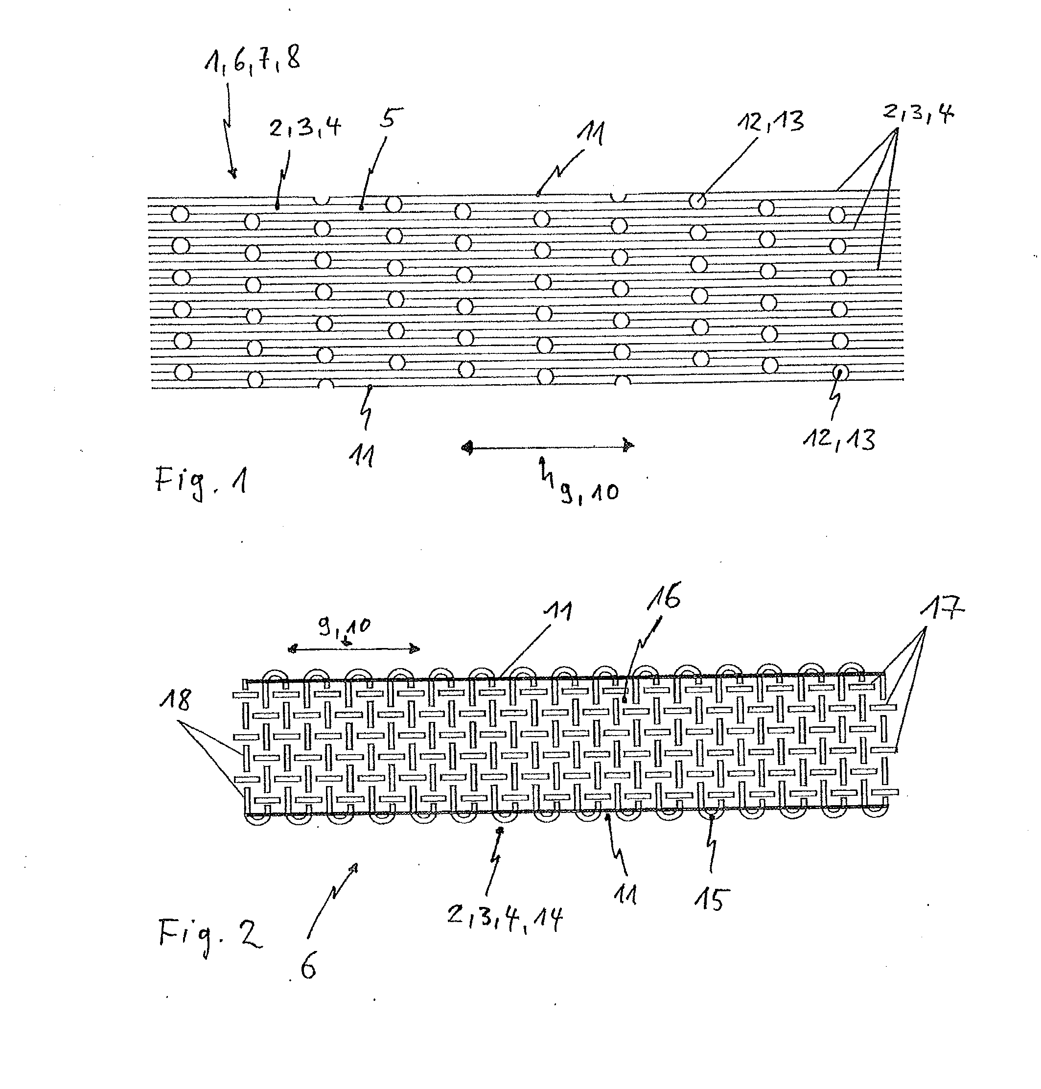
[0127]This exemplary embodiment relates in more detail to FIG. 2 and FIG. 3.

[0128]For manufacturing the filament 6, a woven material 14 as starting material is used as structure 2 to be coated with a thermoplastic material as an enveloping material 16 and subsequent consolidation. The tape-shaped filaments 6 are then cut to the requisite dimensions from the composite.

[0129]The woven material 14 consists of carbon fibers 4, which, as fiber bundles 15 and / or rovings (these terms are used synonymously herein), consist of as few fibers 3 as possible. Particularly well-suited are rovings 15 and / or bundles of 25 tex to 100 tex (1 tex is defined as 1 g per 1,000 meters of fiber length) both as warp thread 17 and as weft 18. Rovings 15 made of carbon fibers 4 of 0.5 k, 1 k or 3 k can be used, wherein 0.5 k and 1 k are to be preferred.

[0130]The woven material 14 is produced in plain weave, twill weave or any other type of weave and attains a weight per unit area of 30 g / m2 up to maximally 50...

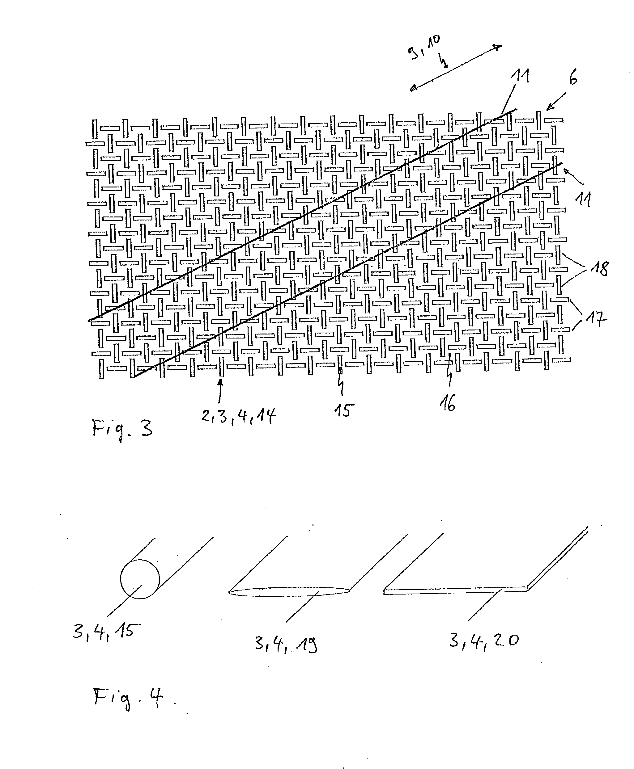
exemplary embodiment 3

[0137]In a refinement of exemplary embodiment 2, another procedural step precedes the process of coating and consolidation of the woven material 14 with the enveloping material. The fiber bundles 15 used for producing the woven material 14 are initially reworked in terms of their shape from a largely round bundle cross-section to a fiber bundle having an elliptical cross-section 19 and / or a fiber bundle having a rectangular cross-section 20, as is illustrated in FIG. 4.

[0138]Preferably, this is achieved by the woven material 14 according to FIG. 3 running loosely over a blower or the woven material being guided through rollers. In the process, the fibers 3 are distributed homogeneously over the given surface. The voids that are initially present in the woven material 14 close virtually completely and the woven material 14 gets flatter.


PUM

PropertyMeasurementUnit
Temperatureaaaaaaaaaa
Lengthaaaaaaaaaa

Abstract

A method is provided for manufacture of an electrically conductive material, including the steps of: (a) providing a structure made of electrically conductive fibers, and (b) producing a carbon-based, electrically conductive matrix at least partially enveloping the electrically conductive fibers. Before or after producing the matrix, at least part of the electrically conductive fibers are interrupted in the direction of possible current flow. Electrically conductive materials obtained in corresponding manner are also provided. An emitter is specified that contains a transparent or translucent housing and an electrically conductive material according to the above. The electrically conductive materials have an increased electrical resistance. These allow emitters of virtually any length to be operated at customary line voltages.

Description

CROSS-REFERENCE TO RELATED APPLICATIONS[0001]This application is a Section 371 of International Application No. PCT / EP2012 / 002802, filed Jul. 4, 2012, which was published in the German language on Feb. 14, 2013, under International Publication No. WO 2013 / 020621 A3 and the disclosure of which is incorporated herein by reference.BACKGROUND OF THE INVENTION[0002]The invention relates to a method for manufacturing an electrically conductive material, an electrically conductive material per se, and an emitter containing an electrically conductive material.[0003]The electrically conductive materials at issue are conceivable for use as electrically heatable elements for use in incandescent lamps or infrared emitters. Accordingly, the electrically conductive materials are suitable, in particular, for the targeted emission of beams in the visible, and in particular in the non-visible, range of wavelengths.[0004]Electrically conductive materials of this type are often based on carbon or cons...

Claims


Application Information

Patent Timeline
IPC IPC(8): H01B13/00H01B5/12
CPCH01B13/0036H01B5/12H05B3/145H05B3/0033H01K3/02Y10T29/49117H01K1/06
Inventor LINOW, SVENKLUMPP, MAIKE
Owner HERAEUS NOBLELIGHT GMBH
Why Eureka
Try Eureka