Corrugated Tube Regenerator for an Expansion Engine

a technology of expansion engine and regenerative heat exchanger, which is applied in the direction of indirect heat exchangers, machines/engines, lighting and heating apparatus, etc., can solve the problems of low capacity gas turbines that are generally considered impractical, limited to constant speed proto-types, and ongoing gas turbine development. , to achieve the effect of low seal leakage, low leakage, and increased pressure capability

Inactive Publication Date: 2014-08-07
KAUFMAN JAY STEPHEN
View PDF6 Cites 4 Cited by
  • Summary
  • Abstract
  • Description
  • Claims
  • Application Information

AI Technical Summary

Benefits of technology

[0010](e) to provide a rotary regenerator having low seal leakage or increased pressure capability;
[0011](f) to provide a rotary regenerator having heat recovering purge flow for matrix lubrication and low seal leakage without loss of engine efficiency;

Problems solved by technology

Low capacity gas turbines are generally considered to be impractical, especially in variable speed automotive use, due to very high turbine speed, inefficient turn-down during deceleration and idling, and high exhaust temperature.
As a result, cycle efficiency is high within turbine stress limitations imposed by the pressure-speed relation, wherein rotor speed is directly proportional to working fluid flow rate and compression ratio and indirectly proportional to turbine diameter.
In the former case micro-turbines for distributed electric generation are gaining wide acceptance, while in the latter case gas turbine development is ongoing and limited to constant speed proto-types.
It is the most expensive component of the gas turbine system, constructed of high temperature alloys with a large number of closely spaced brazed joints and complex header arrangements.
Both fixed and rotary heat exchangers are subject to design compromise to limit thermal stresses.
The ceramic rotary regenerator matrix can withstand elevated turbine exhaust temperature, but off-design operating conditions may impose excessive thermal stress.
In addition, the latter is subject to erosion / corrosion due to seal leakage and is not conducive to heat transfer enhancement geometry and ring gear attachment.

Method used


Image

  • Corrugated Tube Regenerator for an Expansion Engine
  • Corrugated Tube Regenerator for an Expansion Engine
  • Corrugated Tube Regenerator for an Expansion Engine

Examples


Embodiment Construction

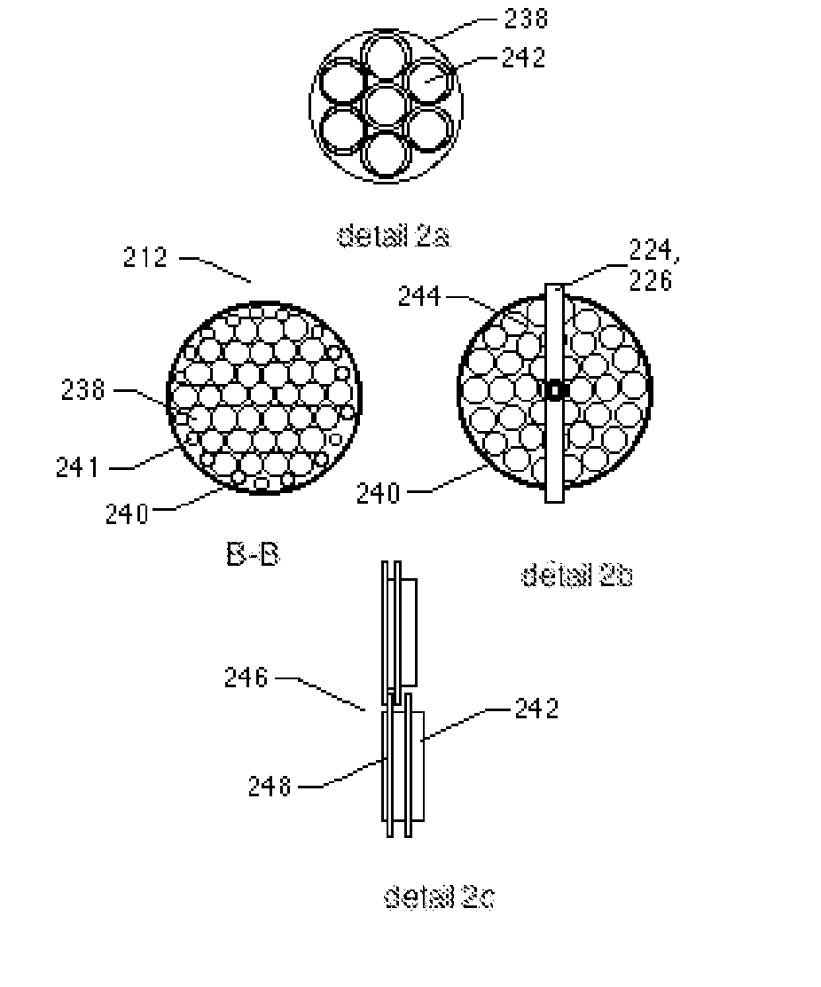
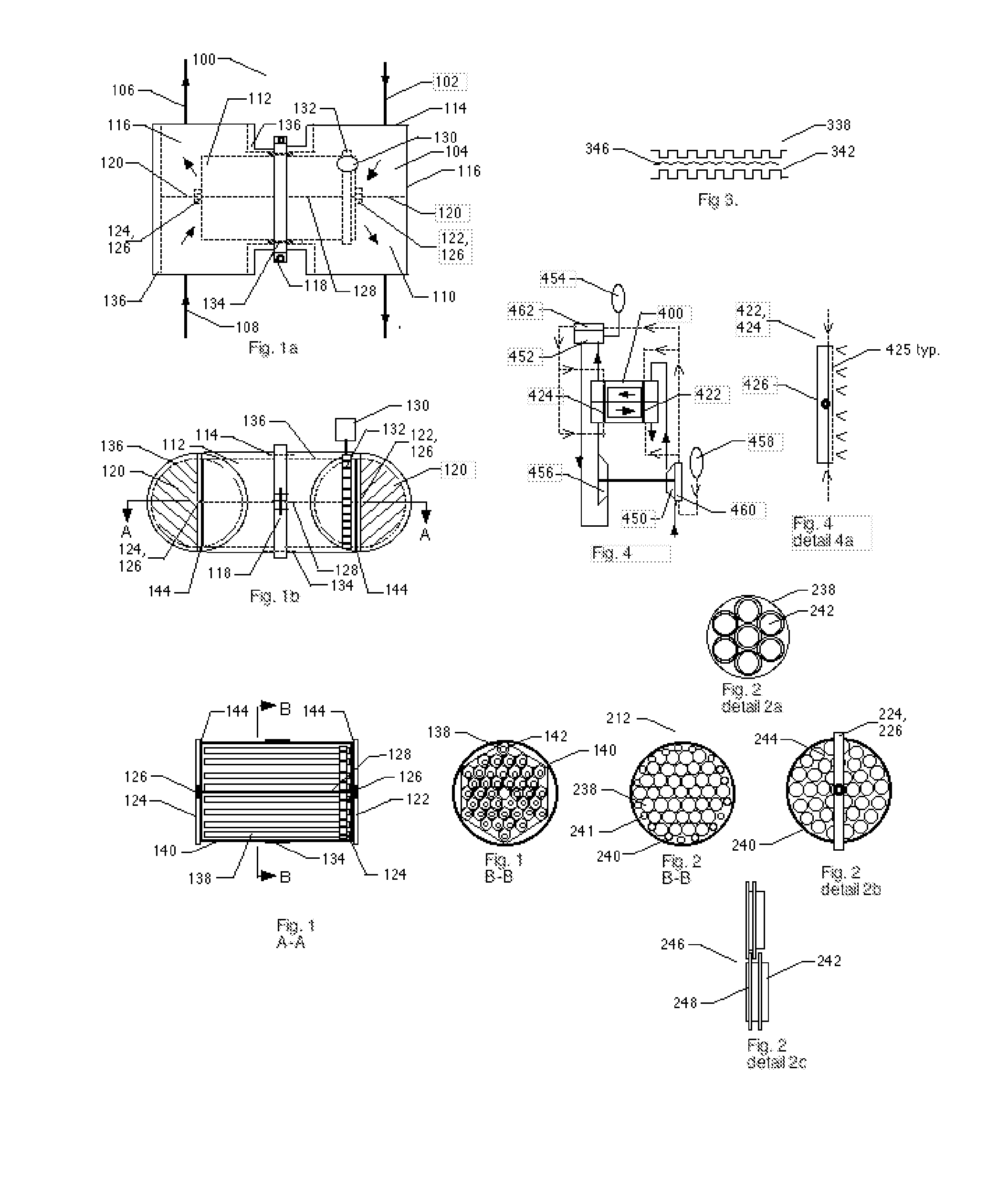
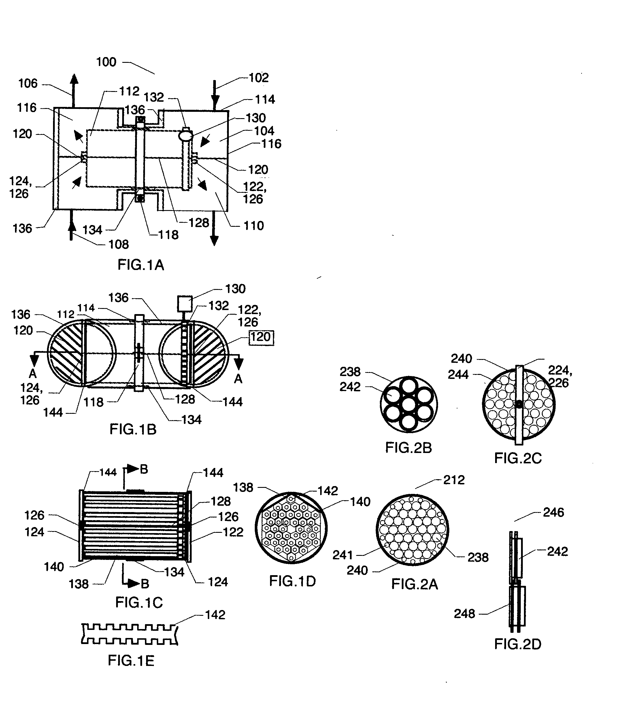
[0029]FIG. 1A and FIG. 1B illustrate working fluid channeling and component arrangement of a preferred embodiment of a rotary regenerator 100 of a prime mover of the present invention. Arrows indicate flow direction of working fluid from a compressor discharge line 102 through a pressurized regenerator channel 104 and discharging to a combustor intake line 106, while working fluid exhaust from a turbine discharge line 108 continues through a depressurized regenerator channel 110 to atmosphere. Heat is transferred from the turbine exhaust to pressurized working fluid within a rotating heat transfer matrix 112. The matrix is contained and supported in a containment vessel 114 constructed of two tee fittings 116 held together by a bolted clamp 118. Clamped stainless steel tee fittings are available from Victaulic Company of Easton, Pennsylvania. Semi-circular baffle plates 120, welded to the fittings and abutted to a colder matrix end support bar 122 and to a hotter matrix end support ...


PUM

PropertyMeasurementUnit
temperatureaaaaaaaaaa
cruising speedaaaaaaaaaa

Abstract

A regenerative heat exchanger for transferring heat from the exhaust gas to the intake working fluid of a prime mover. Application includes gas turbines for both motor vehicles and distributed electric generation. The heat exchanger employs a rotating matrix, which circulates through working fluid exhaust and intake channels while absorbing and rejecting heat between the two channels. Features include corrugated tubes for enhanced heat transfer, minimally welded low stress construction, quick-detach assembly of standard components, and purge flow sealing using recovered heat. Effectiveness exceeding 95% increases thermal efficiency of low-pressure ratio gas turbines.

Description

BACKGROUND OF THE INVENTION[0001]The present invention relates to counter flow regenerative heat exchangers for heat recovery in low capacity prime movers. This includes distributed electric generation and vehicle use, and pertains particularly to an improved regenerator for small gas turbine engines. Low capacity gas turbines are generally considered to be impractical, especially in variable speed automotive use, due to very high turbine speed, inefficient turn-down during deceleration and idling, and high exhaust temperature. The rotary regenerator of the present invention with heat transfer enhancing features resolves these issues, enabling efficient low compression operation with effectiveness greater than 95%. Low stress and compact low cost metallic construction withstands high turbine outlet temperature associated with low compression. As a result, cycle efficiency is high within turbine stress limitations imposed by the pressure-speed relation, wherein rotor speed is directl...

Claims


Application Information

Patent Timeline
Patent Type & Authority Applications(United States)
IPC IPC(8): F28D11/04B21D53/02F28D1/053
CPCF28D11/04F28D1/053B21D53/02F28F1/08F02C7/105F28D19/042F28D19/047F28F1/40Y10T29/4935
Inventor KAUFMAN, JAY STEPHEN
Owner KAUFMAN JAY STEPHEN
Why Eureka
Try Eureka