

Stretchable electronic systems with fluid containment
a technology of electronic systems and fluid containment, applied in the direction of cell components, cell component details, circuit bendability/stretchability, etc., can solve the problems of inability to bind most flexible materials, inability to make conventional silicon based electronic devices incompatible with most flexible materials, and inorganic semiconductors that are not intrinsically soluble in convenient solvents. to achieve the effect of reducing the strain on the one or two
- Summary
- Abstract
- Description
- Claims
- Application Information
AI Technical Summary
Benefits of technology
Problems solved by technology
Method used
Image

Examples
example 1
Stretchable Batteries with Self-Similar Serpentine Interconnects and Integrated Wireless Recharging Systems
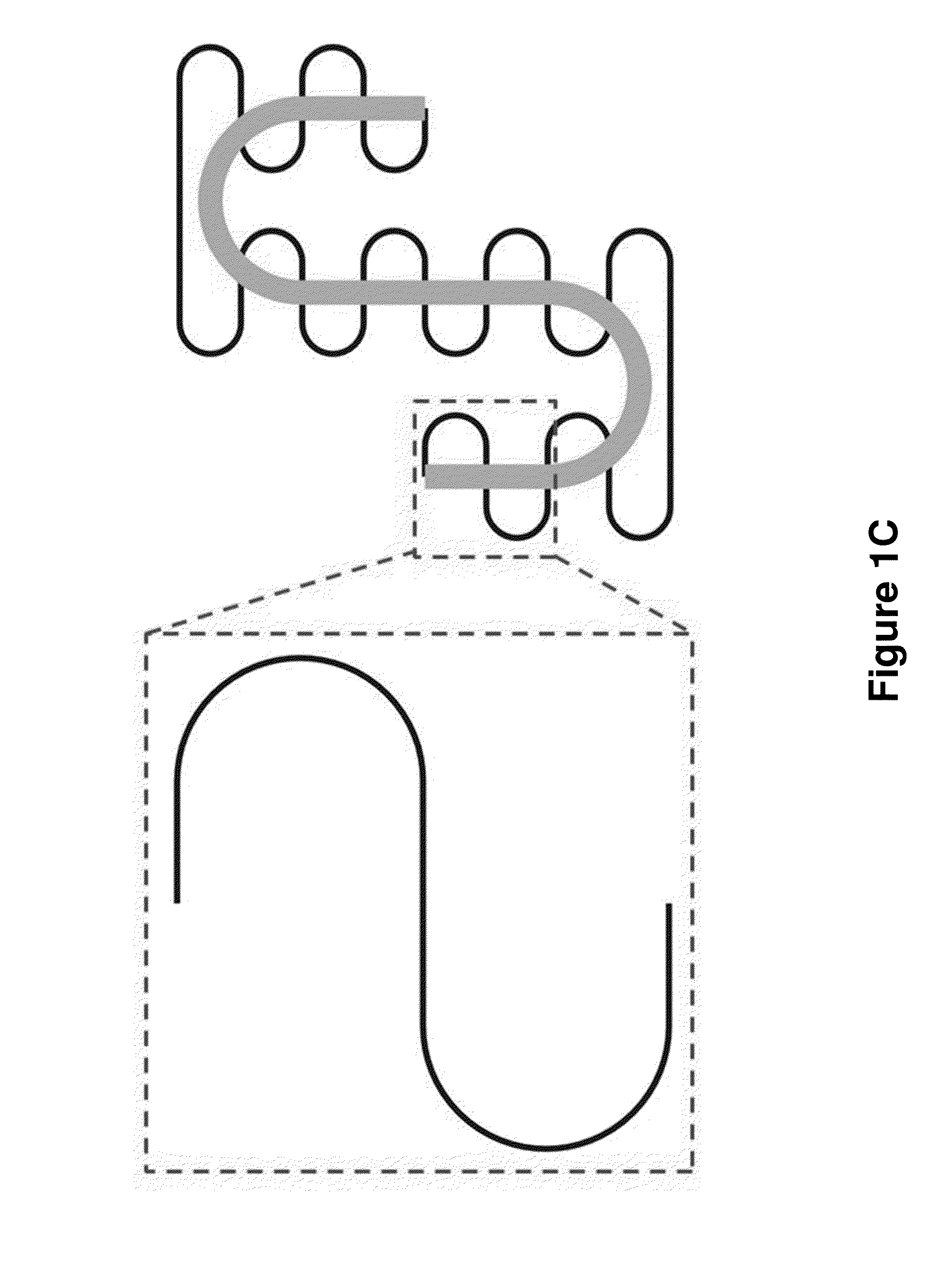
[0166]An important trend in electronics involves the development of materials, mechanical designs and manufacturing strategies that enable the use of unconventional substrates, such as polymer films, metal foils, paper sheets or rubber slabs. The last possibility is particularly challenging because the systems must accommodate not only bending but also stretching, sometimes to high levels of strain (>100%). Although several approaches are available for the electronics, a persistent difficulty is in energy storage devices and power supplies that have similar mechanical properties, to allow their co-integration with the electronics. In this Example, we provide a set of materials and design concepts for a rechargeable lithium ion battery technology that exploits thin, low modulus, silicone elastomers as substrates, with a segmented design of the active materials, and unusual ‘self...
example 2
Device Geometries and Materials Strategies for Stretchable Electronic Systems
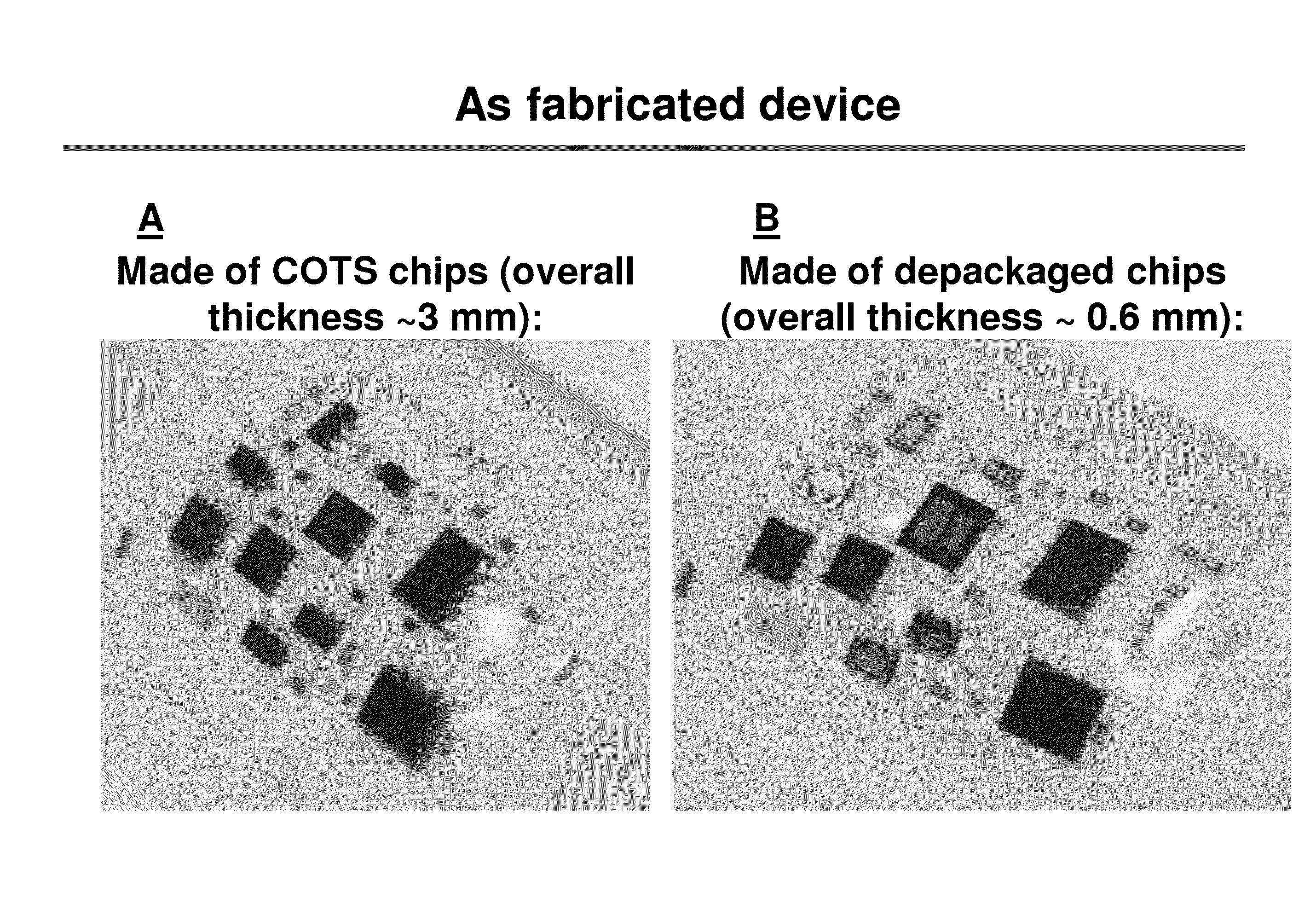
[0241]FIGS. 25 and 27 provide example fabrication process flow diagrams for making some electronic systems of the invention. FIG. 25 provides an overall fabrication flow chart. FIG. 26 illustrates silver epoxy scraping for making the electrical contact between the serpentine interconnects and COTS chips. FIG. 27 illustrates liquid chamber fabrication. The cavity or pouch is formed by laminating a thin piece of elastomer sheet on top of the substrate, and sealing at the surrounding periphery is achieved under heat and pressure with the uncured elastomer as glue. Fluid is injected into the as-formed cavity by injection through the cavity side edge with a syringe.
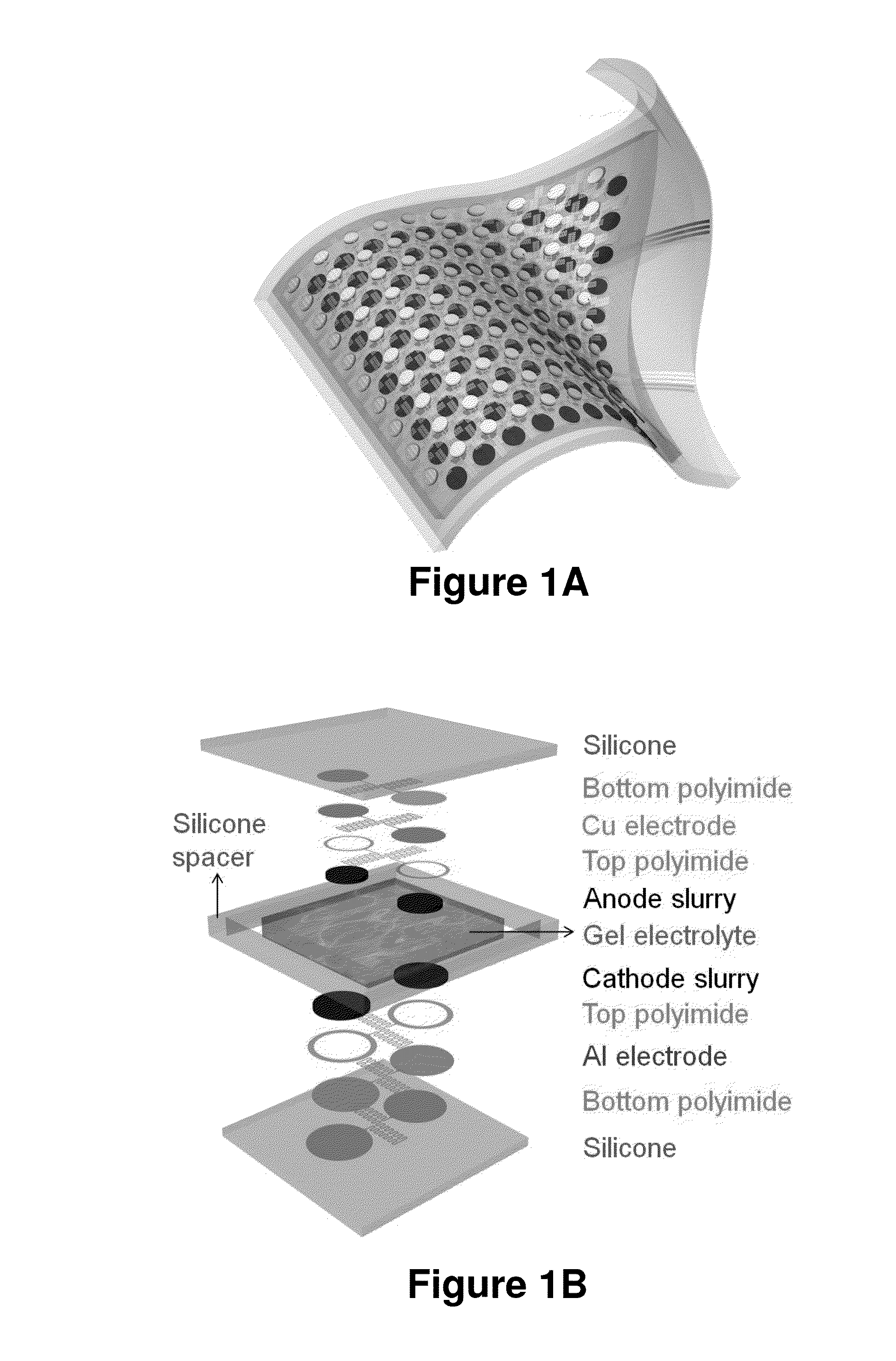
[0242]FIG. 28 illustrates a single battery of the present invention. FIG. 29 Illustrates a battery undergoing ˜100% uniaxial stretching.
[0243]FIG. 30 provides an ECG circuit with wireless power and telecommunication. FIG. 31 provides an example of ECG...
example 3
Electronic Systems Having Fluid Containment
[0257]Electronic devices having fluid containment will now be described with reference to the figures, where reference numerals used to describe FIG. 70 show the same features in multiple embodiments, multiple items within a figure may not be labeled, and the figures may not be drawn to scale.
[0258]FIGS. 70A and 70L show side plan views of systems 102 comprising a substrate 100 with one or more electronic devices or device components 110A, 110B, 110C supported by a surface 105 of the substrate. In the embodiments shown, devices or device components 110A, 110B, 110C are free standing and a fluid containment chamber 135 is formed by a plurality of enclosing structures, such as a top wall 135B and side walls 135A, 135C. The fluid containment chamber 135 at least partially surrounds the devices / components 110A, 110B, 110C within a void space 130 of the chamber that is at least partially filled with a containment fluid 140. In the embodiment of ...
PUM
 Abstract
Description
Claims
Application Information