Eureka AIR delivers breakthrough ideas for toughest innovation challenges, trusted by R&D personnel around the world.

Flexible circuit board and process for producing the same

Active Publication Date: 2014-08-14
ICHIA TECH
View PDF17 Cites 6 Cited by
  • Summary
  • Abstract
  • Description
  • Claims
  • Application Information

AI Technical Summary

Benefits of technology

The present invention provides a flexible circuit board and a process for producing it. By using a coating of polyamic acid and photoresist first instead of a metal layer for electroplating, the process saves time, material, and cost. An adhesion enhancing layer is used for better adhesion between the circuit board and the substrate, resulting in a more stable integration of the circuit. Compared to conventional methods, the present invention achieves reduced thickness and cost by reducing the thickness of the circuit board and the time required for coating. The invention also offers better control over the source of materials.

Problems solved by technology

Metals generally do not easily adhere to conventional precursor substrates.
However these methods result in problems of thick precursor substrates, or difficult and overly long coating processes.
Excess thickness compromises the miniaturization of products.
Difficult and overly long coating processes result in limited production capacity and raised production cost.
The above conventional methods not only cannot overcome problem of necking, but given that the technical and material resources of the precursor substrates are controlled by upstream manufacturers, products that use these precursor substrates are subject to charges by external parties and, due to inability to improve the properties of these products, a fundamental solution for reducing cost is unattainable.
Next, large amount of etching is required to remove the copper and nickel that are not part of the electric circuit on the precursor substrate.
This method creates large amount of wasted copper and nickel, increasing the cost.
In addition to increased cost, the distribution (coverage) of the adhesion enhancing nickel on the substrate is limited, such that improvement upon stable adhesion of the electric circuit is limited, thereby compromising product quality.
Different thermal expansion coefficients between the metal and the substrate may create gaps or other structural disintegration in the electric circuit when the ambience temperature changes, thus, affecting the transmission quality and life span of the product.
This problem is especially prominent in multi-layered flexible printed circuit boards.

Method used


Image

  • Flexible circuit board and process for producing the same
  • Flexible circuit board and process for producing the same
  • Flexible circuit board and process for producing the same

Examples


Embodiment Construction

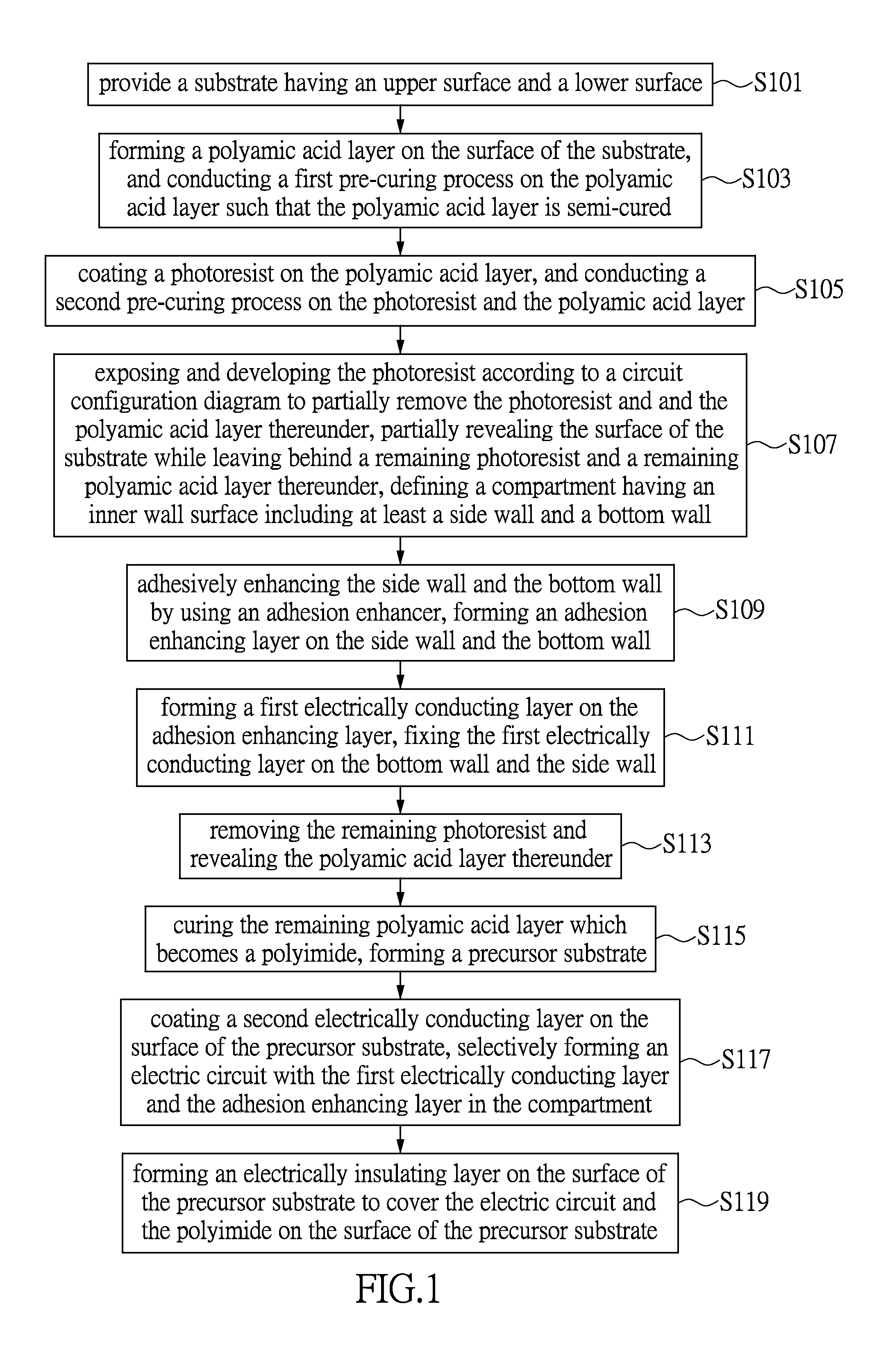
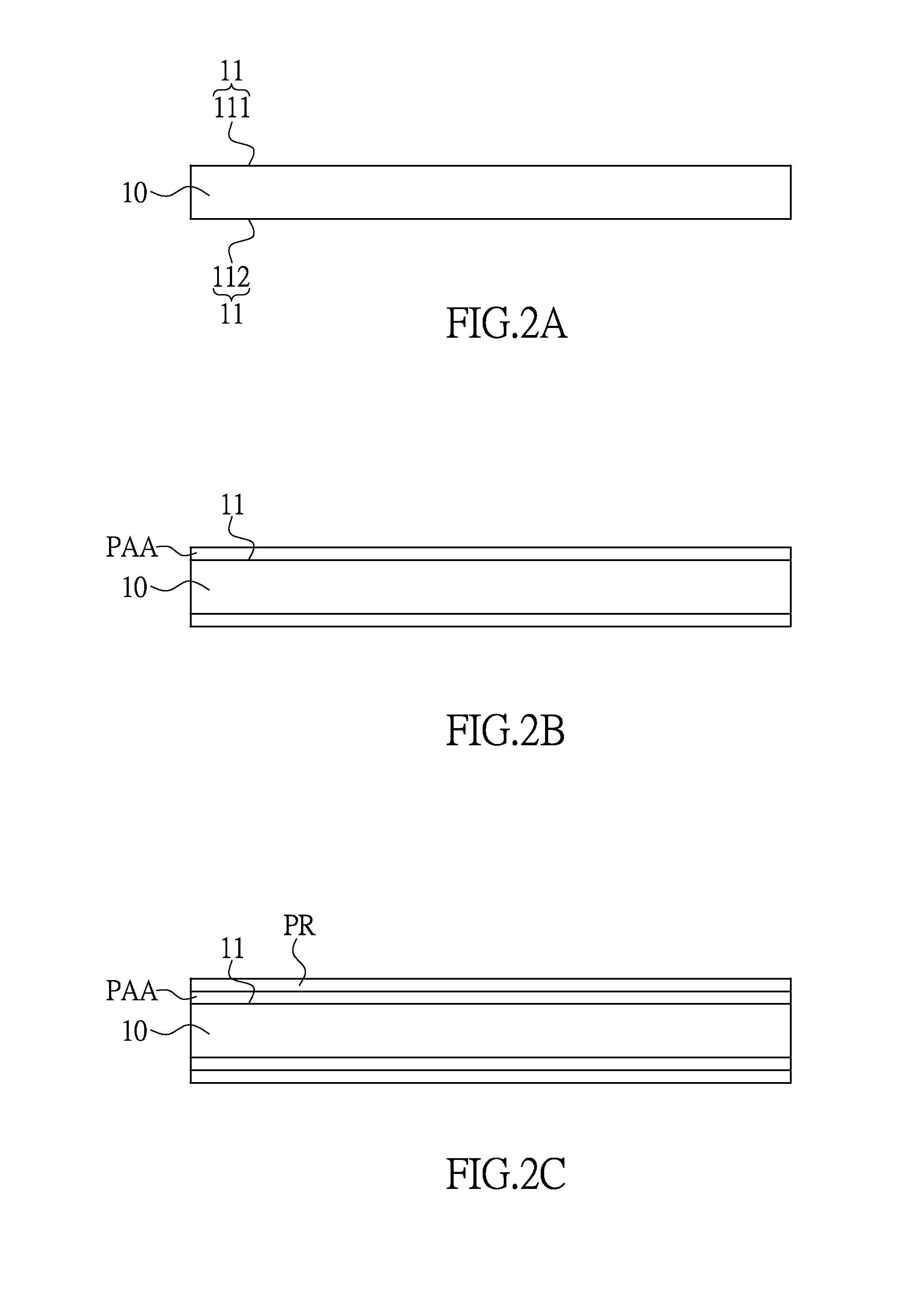
[0019]The aforementioned illustrations and following detailed descriptions are exemplary for the purpose of further explaining the scope of the present disclosure. Other objectives and advantages related to the present disclosure will be illustrated in the subsequent descriptions and appended drawings. FIG. 1, FIG. 2A, FIG. 2B and FIG. 2C show a flowchart of a method of producing a flexible circuit board according to the present disclosure and cross-sectional views corresponding to the steps of the method of producing a flexible circuit board according to the present disclosure. The present disclosure provides a method of manufacturing a flexible circuit board, including the following steps:

[0020]Provide a substrate 10 having a surface 11. The surface 11 includes an upper surface 111 and a lower surface 112 (step S101). The substrate 10 is made of raw material such as Polyimide (PI), Polyethylene Terephthalate Polyester (PET), Polyethylene Naphthalate (PEN), Polytetrafluorethylene (...


PUM

PropertyMeasurementUnit
Thicknessaaaaaaaaaa
Electrical conductivityaaaaaaaaaa
Adhesion strengthaaaaaaaaaa

Abstract

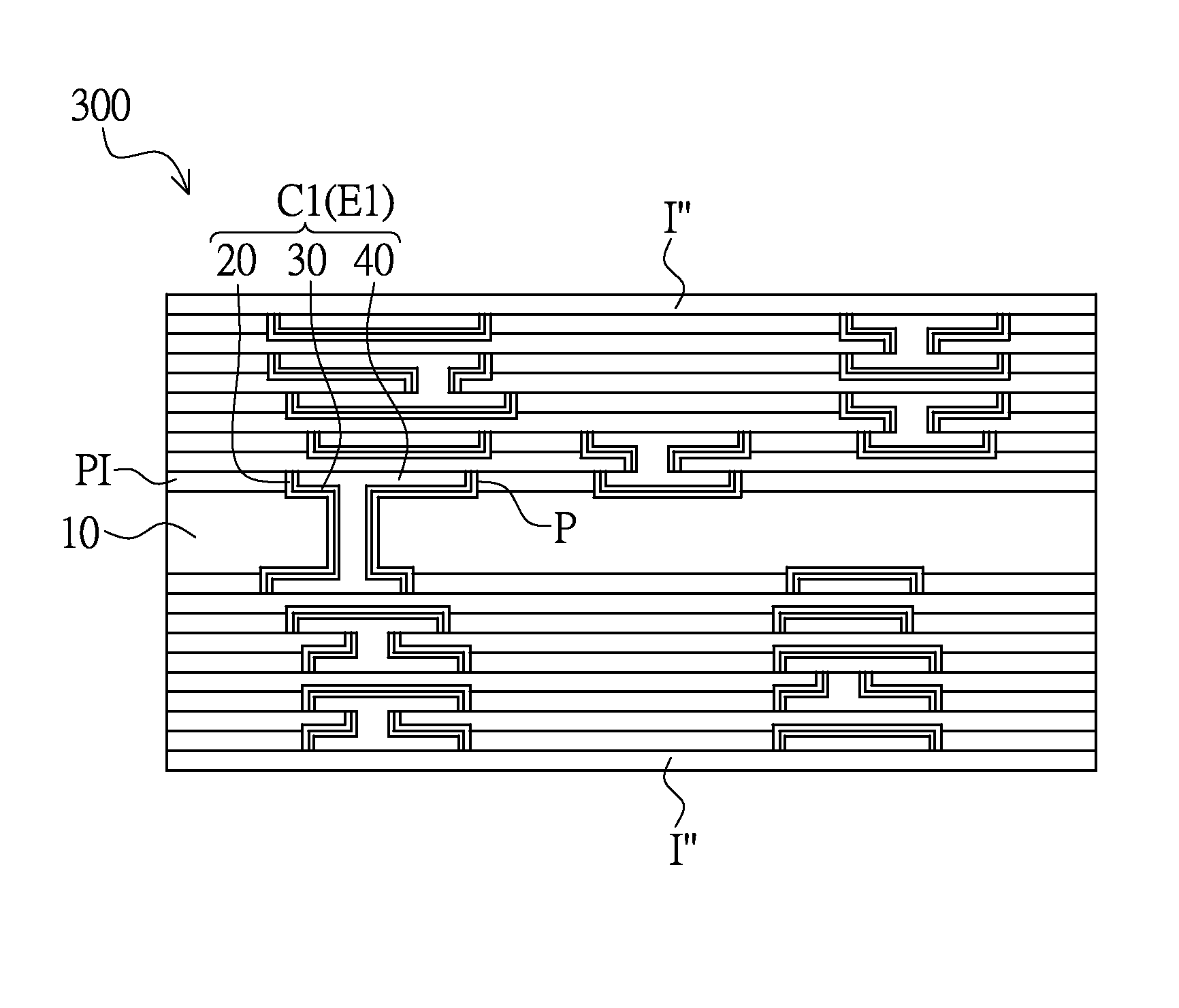
A flexible circuit board comprises a substrate which has a polyimide layer recessed to define at least a compartment. The compartment includes an inner wall surface having a side wall and a bottom wall. The compartment is for containing a multilayer unit, wherein the multilayer unit includes an adhesion enhancing layer formed on the wall of the compartment, a first electrically conducting layer disposed on the adhesion enhancing layer, and a second electrically conducting layer formed on the first electrically conducting layer. The adhesion enhancing layer is palladium. The first electrically conducting layer is nickel. The substrate is composed of polyimide (PI).

Description

BACKGROUND OF THE INVENTION[0001]1. Field of the Invention[0002]The present disclosure relates to a flexible circuit board and a process for producing the same; in particular, to a flexible circuit board formed with a coating-facilitating adhesion enhancing layer on each of the two sides of a compartment having an electric circuit, and a process of producing the flexible circuit board.[0003]2. Description of Related Art[0004]Conventional flexible circuit boards are made by processing precursor substrates. The precursor substrates must be coated with a metal conducting layer to enable subsequent processing. Metals generally do not easily adhere to conventional precursor substrates. Conventional methods of coating metal include metal spraying, sputtering deposition, CVD, vapor deposition, and dry coating. However these methods result in problems of thick precursor substrates, or difficult and overly long coating processes. Excess thickness compromises the miniaturization of products. ...

Claims


Application Information

Patent Timeline
IPC IPC(8): H05K1/02H05K3/00
CPCH05K3/0082H05K1/0271H05K1/0393H05K3/386H05K3/426H05K3/465H05K3/4673H05K2201/0154Y10T428/24521Y10T428/265Y10T428/31678H05K3/46H05K1/028H05K3/20H05K3/22
Inventor CHIU, CHIEN-HWACHAO, CHIH-MINKUO, PEIR-RONGCHIANG, CHIA-HUAHSIAO, CHIH-CHENGKUAN, FENG-PINGLEE, YING-WEIJUANG, YUNG-CHANG
Owner ICHIA TECH
Why Eureka
Eureka Blog
Learn More