Selective laser-assisted transfer of discrete components

a discrete component and laser-assisted technology, applied in the field of electromechanical manufacturing, can solve the problems of insufficient mass for separation from the carrier and transfer, difficult handling, and dice on either end of the size spectrum, and achieve the effects of easy handling, easy shattering, and convenient packaging

Inactive Publication Date: 2014-08-28
NORTH DAKOTA STATE UNIV RES FOUND
View PDF16 Cites 38 Cited by
  • Summary
  • Abstract
  • Description
  • Claims
  • Application Information

AI Technical Summary

Benefits of technology

[0018]Research and experience have shown that brittle materials, such as silicon, can start becoming flexible when material thickness is reduced to less than 100 μm, and are becoming more truly flexible when the thickness is reduced to less than about 50 μm. Articles thicker than 100 μm are not flexible in the sense described herein (e.g., for use on a flex circuit or similar), and can be easily packaged by conventional methods. A strength of the present invention allows for packaging of ultra-thin dice, and other ultra-thin components or articles with thicknesses of less than 50 μm and, even more particularly less than 30 μm, where other methods have not been demonstrated for packaging such ultra-thin dice.
[0019]The present invention can be utilized for handling articles, such as dice, in a wide area range. It will be noted that complications can arise with handling dice on either end of the size spectrum. Small size dice, such as several hundredths of a square mm area, may have insufficient mass for separation from the carrier and transfer over the gap in response to momentum and gravitational forces of the process. When ultra-thin dice are large, such as several square mm or more in area, they can be difficult to handle because of issues with bending and warpage. Examples are provided herein for performing the present inventive transfer for articles having thicknesses of 65 μm, 50 μm, and 25 μm. The present invention provides a gentle transfer mechanism suitable for these ultra-thin articles, with the examples illustrating that the method and apparatus can be practiced across a range of die thicknesses below 100 μm without limitation.
[0020]In contrast to many laser-induced forward transfer mechanisms, the methods of the present invention do not rely on the use of a plume of vaporized material from the dynamic release layer (DRL) to transfer the article(s). Instead, the laser beam (e.g., pulse or pulses) creates a blister in the DRL that is thicker than its laser absorption depth, thus confining the vaporized material within the blister. It is the blister that provides a gentle push of the transfer article (die) off of the dynamic release layer, thus separating the article towards the receiving substrate. The DRL, and more particularly the blistering layer thereof, are subject to only a limited non-penetrating ablation, which creates vapors to form a blister, without rupturing the blister. The laser power and thickness of the blistering layer are selected to prevent ablation vapors from bursting the blister and directly contacting the article of transfer. In prior transfer techniques, high laser power values of between 1 and 50 mJ / pulse DRL evaporation were utilized in performing ablative laser transfer. The present invention uses laser power (energy) of much less than 1 mJ to assure that the blisters do not burst during the process. In particular, embodiments of the present invention have utilized less than 20 μJ / pulse in achieving successful transfers. It can be appreciated from this energy value, that the present process is a gentle one in comparison to ablative release processes, whose energy levels can easily shatter ultra-thin semiconductor dice.

Problems solved by technology

It will be noted that complications can arise with handling dice on either end of the size spectrum.
Small size dice, such as several hundredths of a square mm area, may have insufficient mass for separation from the carrier and transfer over the gap in response to momentum and gravitational forces of the process.
When ultra-thin dice are large, such as several square mm or more in area, they can be difficult to handle because of issues with bending and warpage.

Method used


Image

  • Selective laser-assisted transfer of discrete components
  • Selective laser-assisted transfer of discrete components
  • Selective laser-assisted transfer of discrete components

Examples


embodiment 1

[0106]2. The method of embodiment 1, wherein said blister expands to a substantially fixed distance in response to receiving said low-energy laser beam.

[0107]3. The method of embodiment 1, wherein said blistering layer comprises a polymer, polyimide, or inorganic material selected for ablation in a controlled, and non-explosive, manner in response to irradiation with a laser beam of a given wavelength and pulse energy and which exhibits sufficient elastic behavior that a blister can be formed without rupturing.

[0108]4. The method of embodiment 1, wherein said blistering layer is subject to ablation that is limited to a non-penetrating ablation creating vapors to form said blister without rupturing said blister.

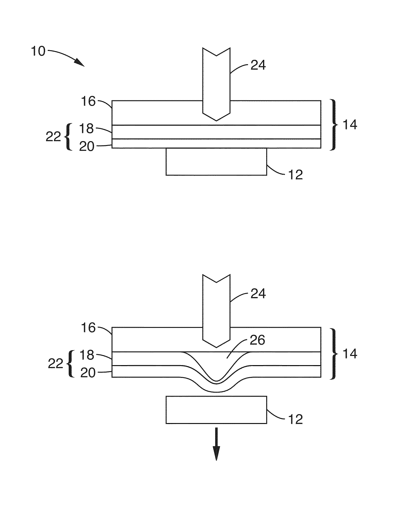
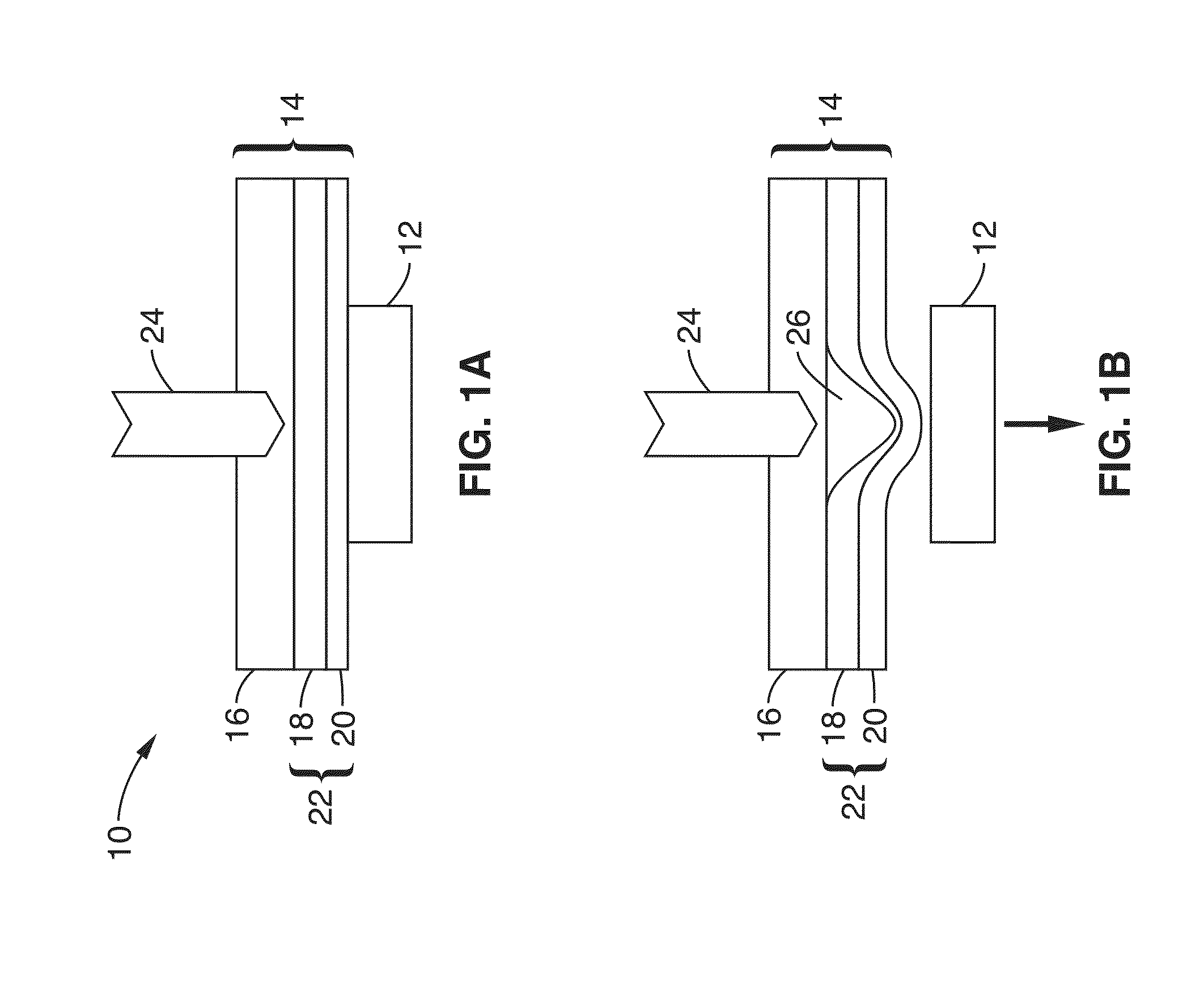
[0109]5. The method of embodiment 1, wherein said blister is formed in response to said low-energy laser beam evaporating a small amount of material from said blistering layer which generates gases that create a blister in said carrier which deforms said adhesive layer of said...

embodiment 8

[0113]9. The method of embodiment 8, wherein said scanning pattern is selected from a group of scanning patterns consisting of straight lines, curved lines, closed curves, circles, triangles, rectangles, and other geometric shapes.

[0114]10. The method of embodiment 1, wherein said low-energy laser beam comprises less than 1 mJ of energy to assure that said blisters do not burst during transfer of said article.

embodiment 10

[0115]11. The method of embodiment 10, wherein said low-energy laser has on the order of 20 μJ of energy per pulse.

[0116]12. The method of embodiment 1, wherein material vaporized by said low-energy laser beam are confined to an interior of said blister within said blistering layer.


PUM

PropertyMeasurementUnit
energyaaaaaaaaaa
energyaaaaaaaaaa
thicknessaaaaaaaaaa

Abstract

Electronic components are often assembled using robotic equipment, such as pick-and-place machines, that is not optimized for components such as ultra-thin semiconductor bare dice. Selective laser-assisted die transfer is described based on the unique blistering behavior of a multilayer dynamic release layer when irradiated by low energy focused laser pulse(s) in which the blister creates translation of the article being placed. Accurate placement results are provided with negligible lateral and angular displacement.

Description

CROSS-REFERENCE TO RELATED APPLICATIONS[0001]This application is a 35 U.S.C. §111(a) continuation of PCT international application number PCT / US2012 / 033147 filed on Apr. 11, 2012, incorporated herein by reference in its entirety, which is a nonprovisional of U.S. provisional patent application Ser. No. 61 / 473,988 filed on Apr. 11, 2011, incorporated herein by reference in its entirety. Priority is claimed to each of the foregoing applications.[0002]The above-referenced PCT international application was published as PCT International Publication No. WO 2012 / 142177 on Oct. 18, 2012 and republished on Feb. 28, 2013, which publications are incorporated herein by reference in their entireties.STATEMENT REGARDING FEDERALLY SPONSORED RESEARCH OR DEVELOPMENT[0003]This invention was made with Government support under Defense Microelectronics Activity (DMEA), Department of Defense Cooperative Agreements Nos. H94003-08-2-0805, H94003-09-2-0905, and H94003-11-2-1102. The Government has certain ...

Claims


Application Information

Patent Timeline
Patent Type & Authority Applications(United States)
IPC IPC(8): B32B37/00
CPCB32B37/025H01L21/67132H01L21/6835H01L24/83H01L2221/68363H01L2221/68381H01L2224/8385H01L2224/83192H01L2224/83001H01L2924/10253H01L2924/01029H01L2221/68318H01L2221/68322H01L2221/68327H01L2924/1461H01L2924/12042H01L2924/3512H01L2924/00B29C65/1606B29C65/1635H01L21/68H01L21/50B29C65/16
Inventor MARINOV, VAL R.SWENSON, ORVENPAVICIC, MARKMILLER, ROSS A.CHEN, ZHIGANGSARWAR, FERDOUSSEMLER, MATTHEW R.
Owner NORTH DAKOTA STATE UNIV RES FOUND
Why Eureka
Try Eureka