Methods of forming carbon coatings

Active Publication Date: 2014-09-11
SAMSUNG ELECTRONICS CO LTD
View PDF1 Cites 17 Cited by
  • Summary
  • Abstract
  • Description
  • Claims
  • Application Information

AI Technical Summary

Benefits of technology

[0034]There is provided a positive electrode active material for a rechargeable lithium battery that includes a chemical carbon coating and thereby may inh

Problems solved by technology

Such additives may also play a role in eliminating side products that are generated during the charge/discharge cycle in the battery, and thereby impair cell performance.
With the exception of phosphoric acid-based positive electrode materials, however, oxide-based positive electrode materials present difficulties in having a carbon coating thereon due to a CO2 generating reaction that occurs during carbonization.
However, under a high voltage circumstance, electrolytes are particularly susceptible to oxidation on the surface of a positive electrode active material (i.e., a composite metal oxide material), and thus there remains an urgent need to develop a coating material that may suppress oxidation in the high voltage positive electrode active material.
On the other hand, the high voltage positive electrode active material usually includes more lithium and thus has a low level of conductivity, resulting in poor battery performance.
According to such conventional methods, when the mixture of the carbon organic precursor and the oxide-based positive electrode material is heat-treated, the positive electrode active material may suffer an oxygen elimination reaction and thereby has a lower capacity.
Moreover, the positive electrode active material may hardly have a uniform carbon coating thereon, and particul

Method used


Image

  • Methods of forming carbon coatings
  • Methods of forming carbon coatings
  • Methods of forming carbon coatings

Examples


example 1

OLO 400 DR 2 h

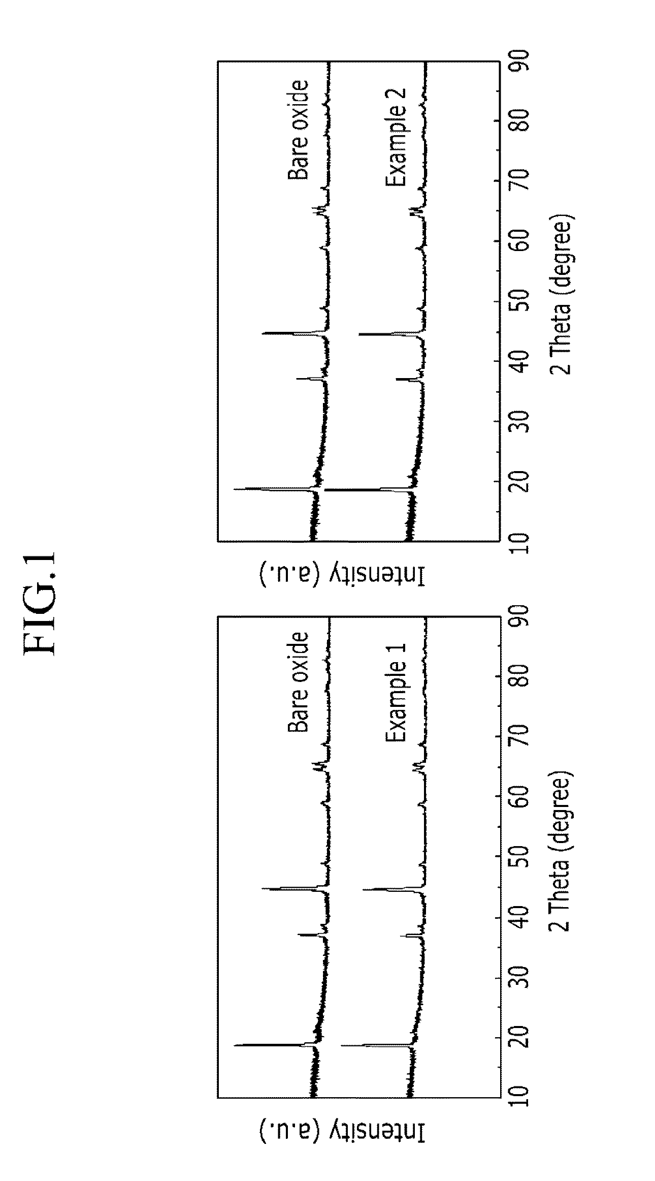
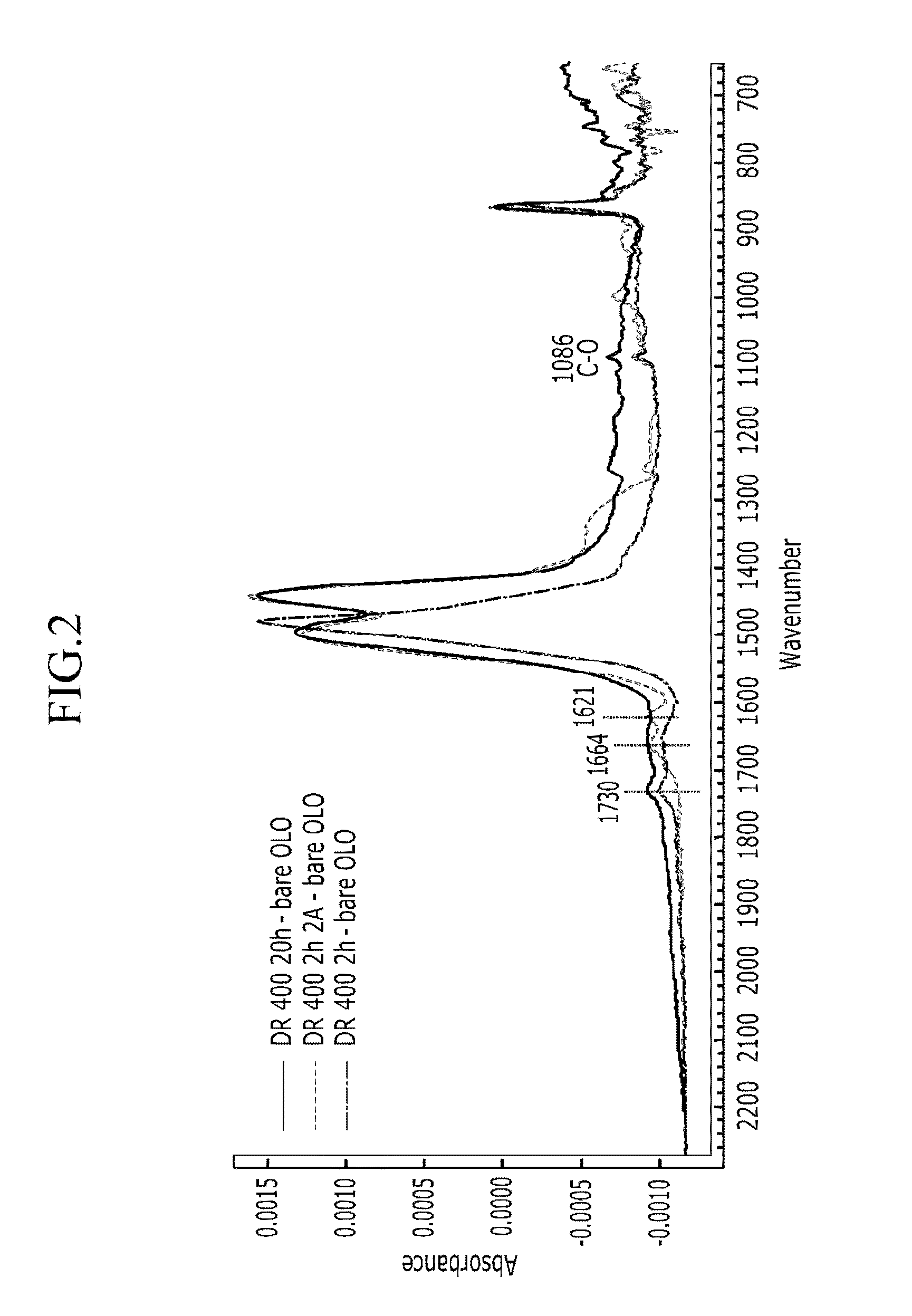
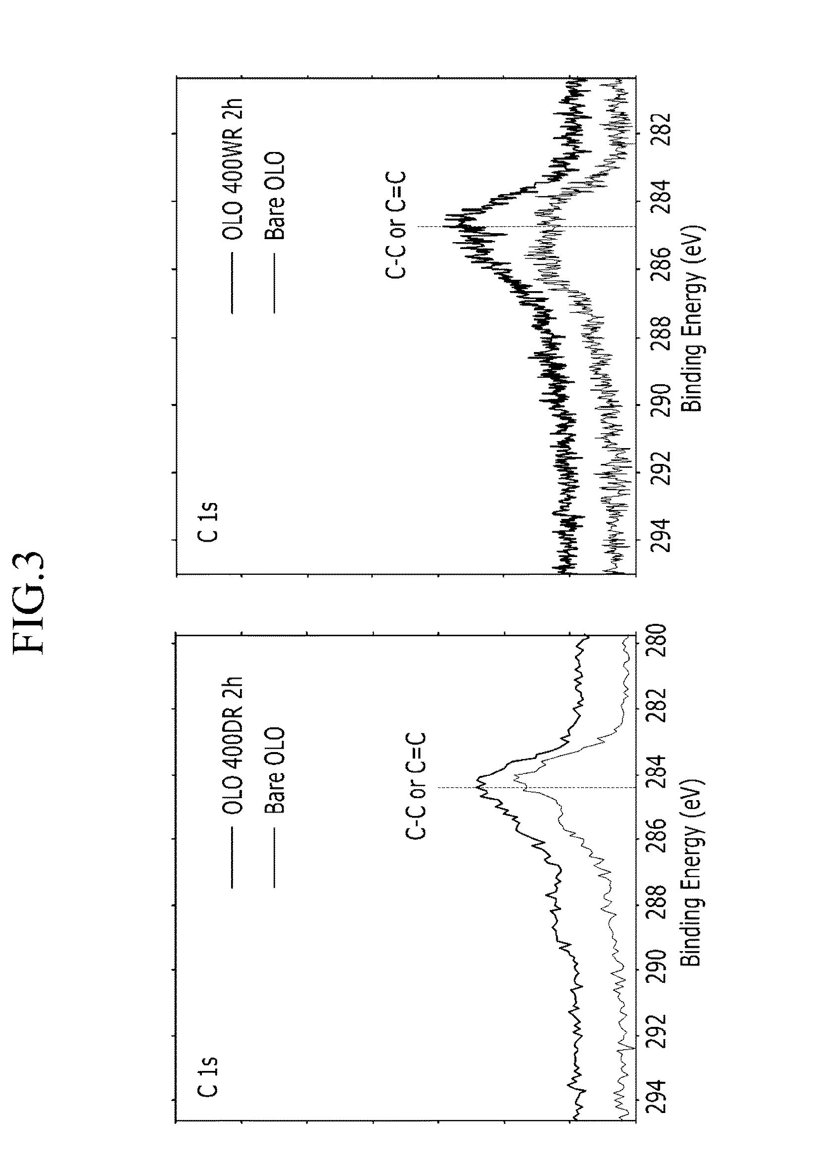
[0105]According to at least one example embodiment, about 1 g to about 5 g of a lithium transition metal composite oxide represented by a chemical formula of Li1.18Ni0.17 Co0.1Mn0.56O2 is disposed in a reactor as illustrated in FIG. 25. A gas mixture having a ratio of CH4:CO2:N2 of about 100 sccm:100 sccm:100 sccm is flowed into the reactor to provide a gas mixture atmosphere in the reactor. A pressure generated by the gas mixture flow in the reactor is about 1 atm. In the atmosphere of the gas mixture, the temperature of the reactor is increased to about 400° C., and the temperature is maintained for 2 hours while the gas mixture continuously flows in the reactor to carry out a heat treatment. As a result, carbon deposition occurs on the composite metal oxide and thereby a carbon coating is formed. Then, the supply of the gas mixture stops, a nitrogen gas flows in while the reactor cools to room temperature, and then a carbon-coated composite metal oxide is recovered....

example 2

OLO 400 WR 2 h

[0106]According to at least one example embodiment, a carbon-coated composite metal oxide is prepared in the same manner as set forth in Example 1, except that the gas mixture of the following composition is flowed in the reactor:

[0107]CH4:H2O:CO2:N2=1.0 sccm:0.8 sccm:0.4 sccm:2.8 sccm

example 3

OLO 400 DR 20 h

[0108]According to at least one example embodiment, a carbon-coated composite metal oxide is prepared in the same manner as set forth in Example 1, except that the heat treatment is performed for 20 hours.


PUM


Abstract

A method of forming a carbon coating includes heat treating lithium transition metal composite oxide Li0.9+aMbM′cNdOe, in an atmosphere of a gas mixture including carbon dioxide and compound CnH(2n+2−a)[OH]a, wherein n is 1 to 20 and a is 0 or 1, or compound CnH(2n), wherein n is 2 to 6, wherein 0≦a≦1.6, 0≦b≦2, 0≦c≦2, 0≦d≦2, b, c, and d are not simultaneously equal to 0, e ranges from 1 to 4, M and M′ are different from each other and are selected from Ni, Co, Mn, Mo, Cu, Fe, Cr, Ge, Al, Mg, Zr, W, Ru, Rh, Pd, Os, Ir, Pt, Sc, Ti, V, Ga, Nb, Ag, Hf, Au, Cs, B, and Ba, and N is different from M and M′ and is selected from Ni, Co, Mn, Mo, Cu, Fe, Cr, Ge, Al, Mg, Zr, W, Ru, Rh, Pd, Os, Ir, Pt, Sc, Ti, V, Ga, Nb, Ag, Hf, Au, Cs, B, Ba, and a combination thereof, or selected from Ti, V, Si, B, F, S, and P, and at least one of the M, M′, and N comprises Ni, Co, Mn, Mo, Cu, or Fe.

Description

CROSS-REFERENCE TO RELATED APPLICATION[0001]This application claims priority from Korean Patent Application Nos. 10-2013-0025139 and 10-2013-0121468, filed in the Korean Intellectual Property Office on Mar. 8, 2013 and Oct. 11, 2013, respectively, the entire contents of which are incorporated herein by reference in their entirety.BACKGROUND[0002]1. Field[0003]Methods of forming carbon coatings, a composite metal oxide coated with carbon, and / or a lithium ion battery including the same are disclosed.[0004]2. Description of the Related Art[0005]Lithium ion batteries (LiB) typically have high energy density and may be easily fabricated into various designs, and thus have been widely used as an electricity source for portable devices. Recently, as the application of LiB has been extended to power supplies for an electric vehicle and for electrical power storage portable devices, vigorous research has been made on materials that make it possible to realize high energy density and a long ...

Claims


Application Information

Patent Timeline
IPC IPC(8): H01M4/36
CPCH01M4/366H01M4/485H01M4/505H01M4/525H01M4/625H01M10/052Y02E60/10Y02T10/70
Inventor SON, IN HYUKMUN, JUN YOUNGPARK, JIN-HWANPAK, CHAN HOLEE, SEUNG JAEKANG, HYO RANG
Owner SAMSUNG ELECTRONICS CO LTD
Why Eureka
Try Eureka