Anode for lithium secondary battery and lithium secondary battery including the same

a lithium secondary battery and anode technology, applied in the direction of batteries, cell components, sustainable manufacturing/processing, etc., can solve the problems of degradation of battery performance and cycle life, difficult penetration of electrolyte solution into the electrode, etc., to improve the charge characteristics and cycle life of lithium secondary batteries, improve the porosity of the electrode surface, and improve the effect of ion mobility

Active Publication Date: 2014-09-25
LG ENERGY SOLUTION LTD
View PDF5 Cites 44 Cited by
  • Summary
  • Abstract
  • Description
  • Claims
  • Application Information

AI Technical Summary

Benefits of technology

[0015]Since an anode according to an embodiment of the present invention may include a multi-layered active material layer including two kinds of anode active materials having different press densities and average particle diameters on an electrode current collector, porosity of the surface of the electrode may be improved even after a press process to improve ion mobility into the electrode. Thus, charge characteristics and cycle life of a lithium secondary battery may be improved.

Problems solved by technology

However, since it has been known that a battery short circuit may occur due to the formation of dendrites and there is a risk of explosion due to the short circuit, the lithium metal is being replaced by a carbon-base compound capable of reversibly intercalating and deintercalating lithium ions as well as maintaining structural and electrical properties.
Since such a phenomenon may be further intensified when the thickness of the electrode is high, an electrolyte solution may be difficult to penetrate into the electrode.
Accordingly, ion transfer path may not be secured and thus, ions may not be smoothly transferred to cause degradation of battery performance and cycle life.

Method used


Image

  • Anode for lithium secondary battery and lithium secondary battery including the same
  • Anode for lithium secondary battery and lithium secondary battery including the same
  • Anode for lithium secondary battery and lithium secondary battery including the same

Examples


example 1

[0061]97.3 parts by weight of a first anode active material (artificial graphite) in which anode density was 1.79 g / cc when a pressure of 12.3 MPa was applied, 0.7 parts by weight of a conductive agent (Super-P), 1.0 part by weight of a thickener (carboxymethyl cellulose), and 1.0 part by weight of a binder (styrene-butadiene rubber) were mixed to prepare a first anode active material slurry.

[0062]Subsequently, 97.3 parts by weight of a second anode active material (artificial graphite) in which anode density was 1.51 g / cc when a pressure of 12.3 MPa was applied, 0.7 parts by weight of a conductive agent (Super-P), 1.0 part by weight of a thickener (carboxymethyl cellulose), and 1.0 part by weight of a binder (styrene-butadiene rubber) were mixed to prepare a second anode active material slurry.

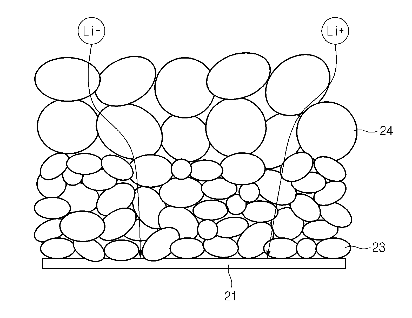
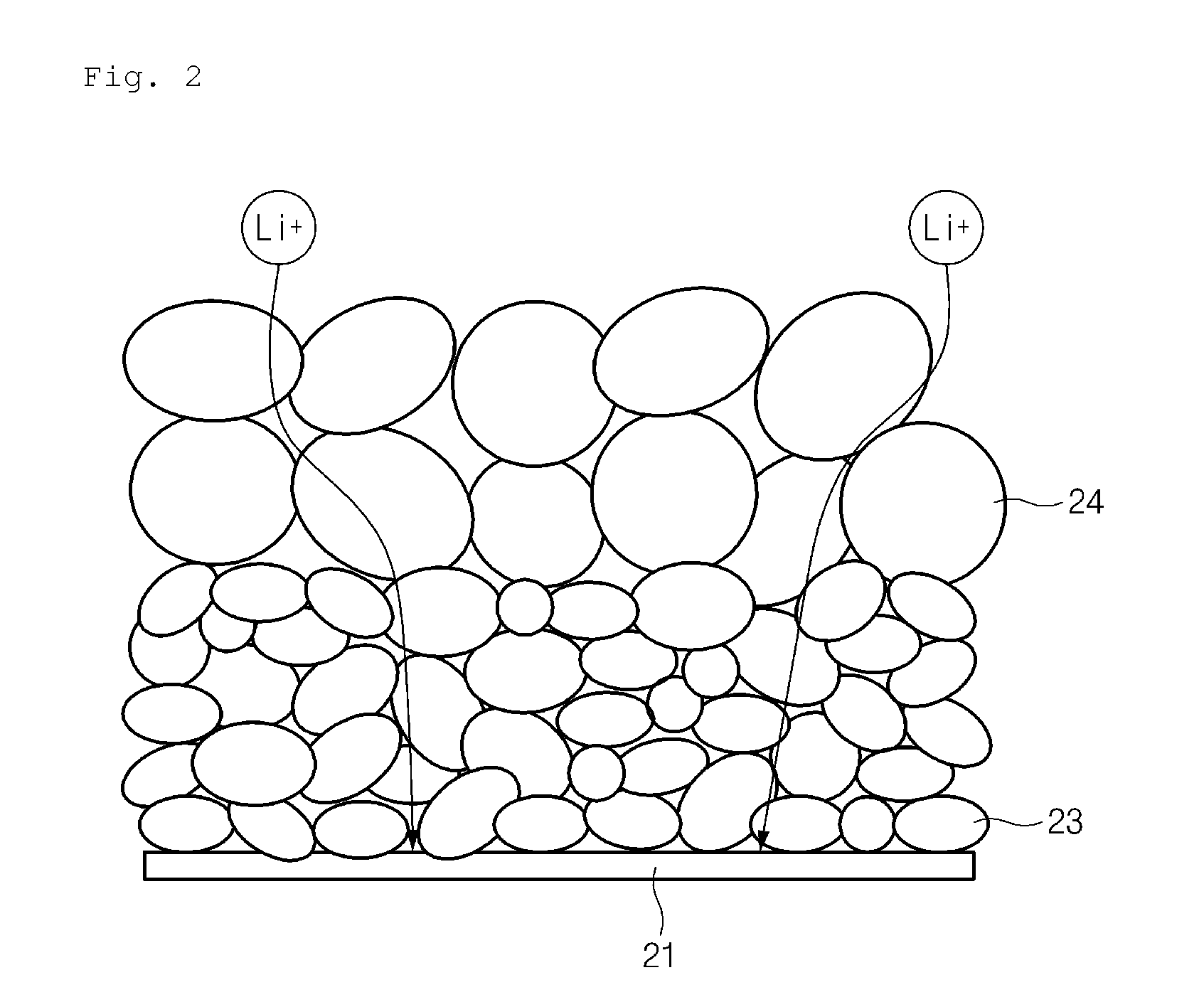
[0063]A copper current collector was sequentially coated with the first anode active material slurry and the second active material slurry, and then dried to form a multi-layered active mater...

experimental example 1

Press Density and Average Particle Diameter Measurement

[0070]Press densities of particles of the anode active materials prepared in Example 1 and Comparative Examples 1 and 2 were measured using a powder resistivity meter, MCP-PD51, by Mitsubishi Chemical Corporation.

[0071]With respect to the above powder resistivity meter, a predetermined amount of anode active material powder was put in a cylinder-type load cell, a force was continuously applied thereto, and density was measured while particles were pressed. Since the particles were less pressed at the same pressure as the strength of the anode active material particles was high, the measured density may be low. In this case, the applied pressure was in a range of about 12 MPa to about 16 MPa.

[0072]Average particle diameters of the anode active materials prepared in Example 1 and Comparative Examples 1 and 2 were measured using a laser diffraction method.

[0073]The press densities and average particle diameters of the particles thu...

experimental example 2

Charge Characteristics

[0074]In order to evaluate charge characteristics of the secondary batteries prepared in Example 1 and Comparative Examples 1 and 2, the secondary batteries prepared in Example 1 and Comparative Examples 1 and 2 were charged at 0.1 C to 4.2 V / 0.05 C at 23° C. under a constant current / constant voltage (CC / CV) condition and then discharged at a constant current (CC) of 0.1 C to a voltage of 3 V to measure capacities twice. Thereafter, the secondary batteries were charged at 0.5 C to 4.2 V / 0.05 C under a CC / CV condition and then discharged at a CC of 0.2 C to a voltage of 3 V to measure 0.5 C rate charge characteristics. The results thereof are present in FIG. 3.

[0075]Referring to FIG. 3, when charged at a constant current of 0.5 C rate, constant current charge time of the battery of Example 1 was longer than those of the batteries of Comparative Examples 1 and 2. Therefore, it may be confirmed that charge characteristics of the battery of Example 1 having an anod...


PUM

PropertyMeasurementUnit
pressureaaaaaaaaaa
discharge voltageaaaaaaaaaa
electrode potentialaaaaaaaaaa

Abstract

Provided is an anode for a lithium secondary battery composed of a multi-layered structure including an electrode current collector, a first anode active material layer including a first anode active material formed on the electrode current collector, and a second anode active material layer including a second anode active material having relatively lower press density and relatively larger average particle diameter than the first anode active material.Since an anode according to an embodiment of the present invention may include a multi-layered active material layer including two kinds of anode active materials having different press densities and average particle diameters on an electrode current collector, porosity of the surface of the electrode may be improved even after a press process to improve ion mobility into the electrode. Thus, charge characteristics and cycle life of a lithium secondary battery may be improved.

Description

CROSS-REFERENCE TO RELATED APPLICATIONS[0001]The present application is a continuation of International Application No. PCT / KR2014 / 000636 filed on Jan. 22, 2014, which claims the benefit of Korean Patent Application No. 10-2014-0007308, filed on Jan. 21, 2014 and Korean Patent Application No. 10-2013-0008785, filed on Jan. 25, 2013, the disclosures of which are incorporated herein by reference.TECHNICAL FIELD[0002]The present invention relates to an anode for a lithium secondary battery and a lithium secondary battery including the same, and more particularly, to an anode including a multi-layered active material layer, in which press densities and average particle diameters of anode active materials are different from each another, and a lithium secondary battery including the anode.BACKGROUND ART[0003]In line with an increase in the price of energy sources due to the depletion of fossil fuels and amplification of interests in environmental pollution, environmentally-friendly alter...

Claims


Application Information

Patent Timeline
Patent Type & Authority Applications(United States)
IPC IPC(8): H01M4/36H01M4/04H01M4/583
CPCH01M10/052H01M4/0435H01M4/1393H01M4/366H01M4/583H01M4/622H01M2004/021H01M2220/20H01M4/0404H01M4/587H01M4/133Y02E60/10Y10T29/49117H01M10/0525Y02T10/70Y02P70/50
Inventor AHN, BYOUNG HOONBAE, JOON SUNGKOO, CHANG WAN
Owner LG ENERGY SOLUTION LTD
Why Eureka
Try Eureka