Determining an electromagnetic response of a sample

a sample and electromagnetic response technology, applied in the direction of material analysis, material analysis using wave/particle radiation, instruments, etc., can solve the problems of inability to model electron pulses, neglected field due to electrons themselves, and inability to insert substrates and electrically large structures, etc., to achieve the effect of avoiding time-consuming search, facilitating the adjustment of optimized input parameters of practical measurement, and avoiding optimizing input parameters during measuremen

Inactive Publication Date: 2014-10-02
MAX PLANCK GESELLSCHAFT ZUR FOERDERUNG DER WISSENSCHAFTEN EV
View PDF10 Cites 5 Cited by
  • Summary
  • Abstract
  • Description
  • Claims
  • Application Information

AI Technical Summary

Benefits of technology

[0039]The major advantage of the present invention over the reported results of theoretical PINEM [1, 7] is the consideration of scattered field caused by both the electron and electromagnetic sources, which allows investigating the temporal dynamics of EEL / EEG spectra with respect to the intensity of the incident electromagnetic excitation, e.g. laser field. Of practical importance is the computation of the intensities of the incident electromagnetic excitation field needed to overcome the scattered field due to the electrons. Furthermore, the investigation of the transition from energy loss spectra probed in the absence of any external radiation fields to the energy loss and gain dynamics in the presence of the laser field and arbitrary structures is made possible by the combination of the presented invention and any finite-difference frequency-domain software commercially available.
[0040]According to a preferred embodiment of the invention, the electron pulse excitation is represented by a charge cloud, e.g. a Gaussian charge distribution, which is treated as a current density function derived from a Gaussian electron wavefunction. Alternatively, the charge cloud can be characterized by a linear or quadratic projection. The aforementioned charge clouds can be used to consider wavefunctions for the electrons other than Gaussian, such as rectangular wavefunction, if experimentally achievable.
[0041]Advantageously, the electron and radiation excitations can be provided with multiple characteristics. As an example, the electromagnetic radiation excitation is not restricted to a certain wavelength range, but rather selected from one of terahertz, microwave, optical, Ultraviolet, and X-rays radiation. Furthermore, according to preferred embodiments of the invention, the electron pulse and / or radiation excitation can have a continuous-wave shape or a pulsed shape.
[0042]According to a preferred application of the invention, the inventive method includes a step of simulating photon induced near-field electron microscopy (PINEM) spectra of the sample structure by superimposing the electron pulse response and radiation responses provided with the simulation steps. Preferably, the inventive method includes a step of simulating electron-energy-loss spectra or the photon induced / assisted near-field electron microscopy spectra at intensities of the electromagnetic radiation excitation at which both of the electron pulse excitation and the electromagnetic radiation excitation have equal or comparable contributions to the electromagnetic response.
[0043]According to a particularly preferred embodiment of the invention, particular excitation parameters of the electron pulse excitation and the electromagnetic radiation excitation are selected in dependency on the calculated electromagnetic response of the sample structure. The excitation parameters are selected such that the calculated electromagnetic response is optimized in terms of the information content to be obtained. In other words, with the use of the selected excitation parameters, the electromagnetic response is characterized by a predetermined significance. The term “significance of the calculated electromagnetic response” refers to the interpretability of the calculated electromagnetic response. Depending on the task of applying the inventive method, the electromagnetic response is considered to be significant if it includes the information content to be obtained. With the embodiment of selecting excitation parameters, the adjustment of optimized input parameters of a practical measurement is essentially facilitated. A time consuming search for optimized input parameters during the measurement can be avoided.
[0044]Preferably, the predetermined significance of the calculated electromagnetic response is obtained, when the calculated electromagnetic response has a maximum spatial, temporal and / or energy resolution. With this embodiment, the inventive method provides optimized spectra. As an alternative, the calculated electromagnetic response is considered to be significant if it shows an interference pattern. As a further alternative, the excitation parameters can be optimized so that the calculated electromagnetic response enables a decomposition of certain modes of the sample structure. Examples of such modes are cases of radiation-free modes, like so called “toroidal modes”.

Problems solved by technology

Firstly, with conventional frequency domain methods like Boundary element methods [3], finite element methods [4], and discrete dipole approximations [5], electron pulses cannot be modeled. Neither can pulsed radiation be considered. Insertion of substrates and electrically large structures is also a problem for methods like discrete dipole approximation.
However, the field due to the electrons themselves had to be neglected.
Another practical problem of the conventional EELS / EEGS and PINEM techniques is related to the complex dependencies of sample responses on input parameters of the electron pulse and electromagnetic excitations (excitation parameters).
Depending on the input parameters, the interpretability or significance of the measured signals can be strongly limited, or the selection of optimized input parameters resulting in measured signals having a sufficient significance can be time consuming.

Method used


Image

  • Determining an electromagnetic response of a sample
  • Determining an electromagnetic response of a sample
  • Determining an electromagnetic response of a sample

Examples


Embodiment Construction

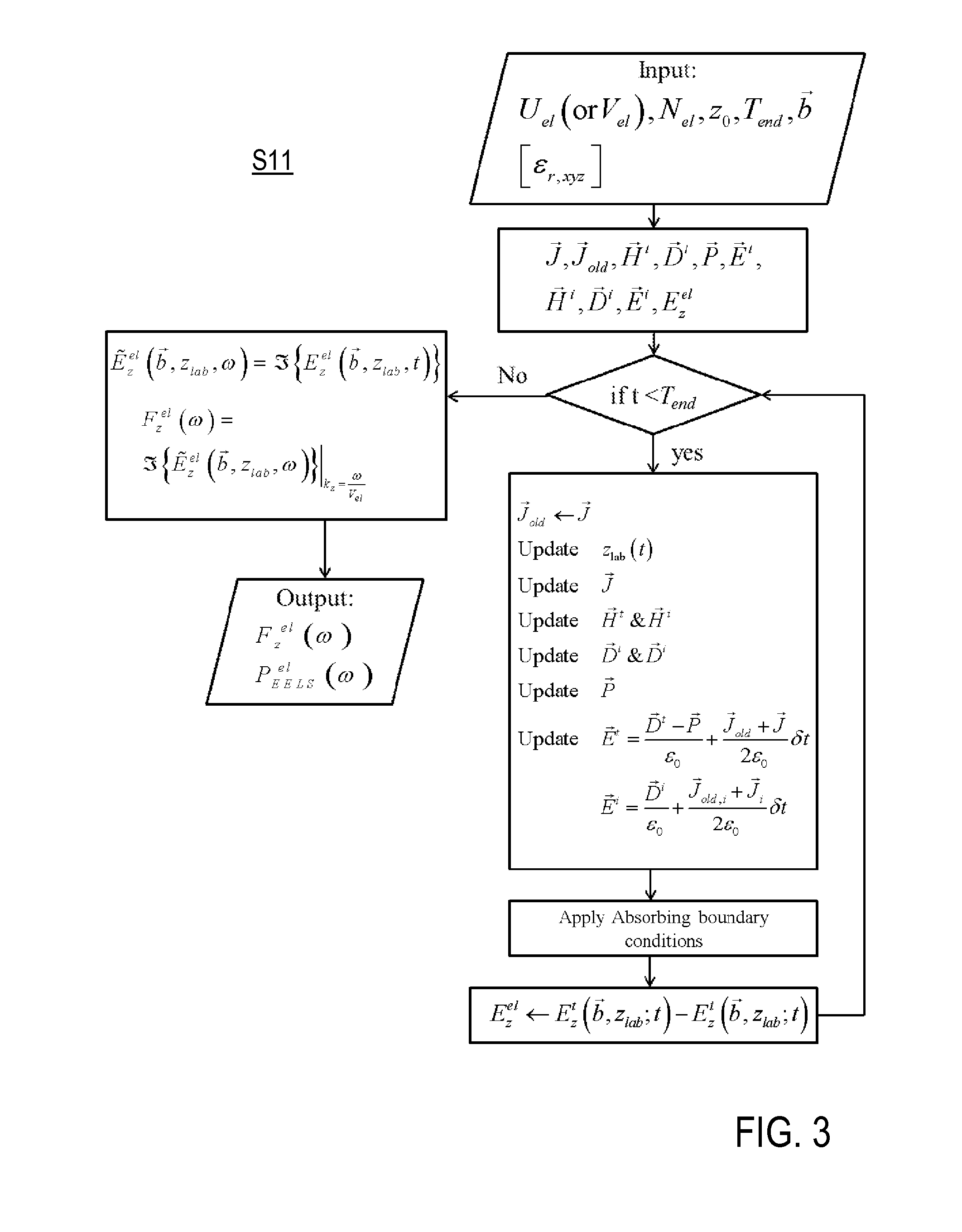
[0057]Features of preferred embodiments of the invention are described here with particular reference to the mathematical background of the inventive methods. The practical implementation of the inventive methods can be obtained with commercial software, like e.g. Agilent EEsof EDA's electromagnetic Professional, Lumerical FDTD solutions, or OptiFDTD, running on computing circuits. Details of the measuring apparatus and the operation thereof are not described as far as they are known from prior art techniques, e.g. from conventional electron microscopes.

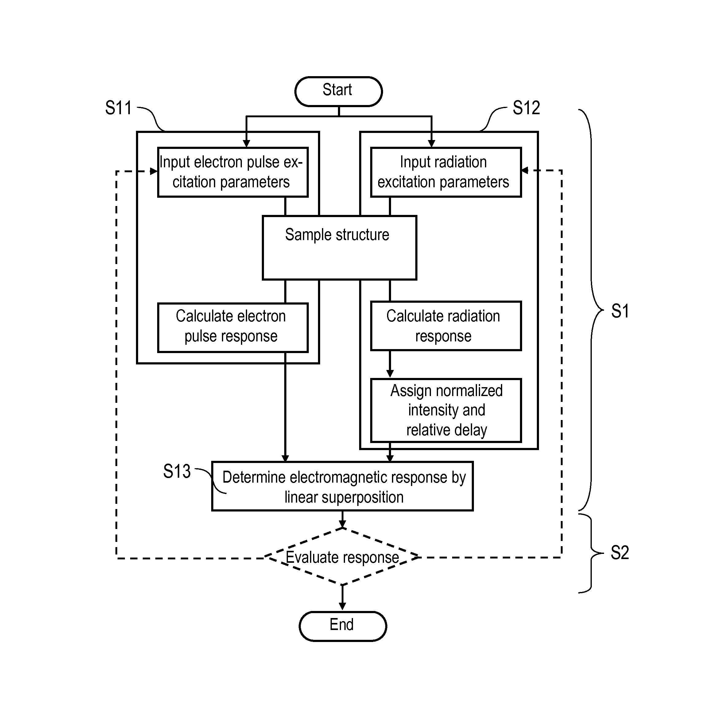
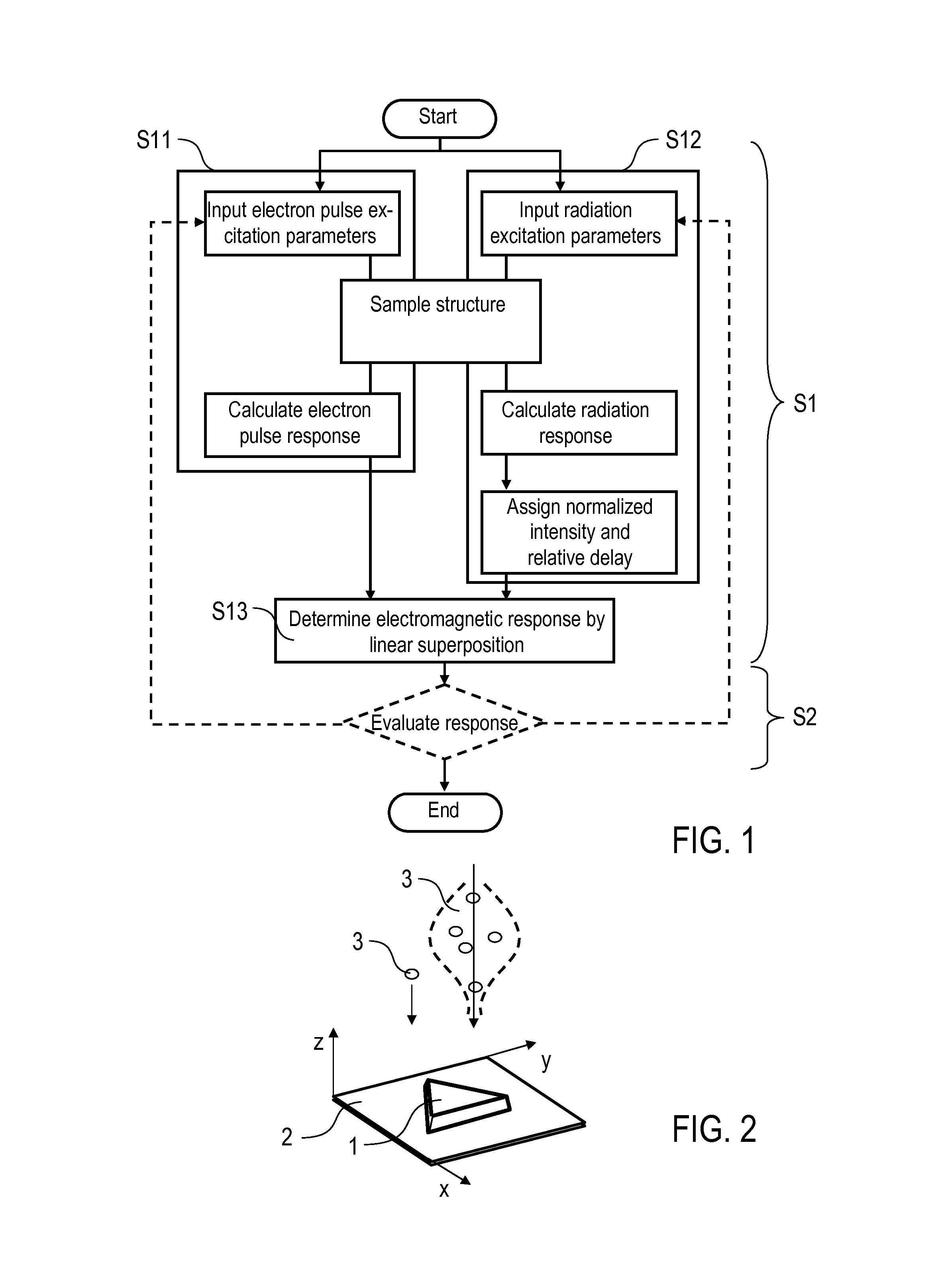
[0058]FIG. 1 schematically illustrates a method (S1) of determining an electromagnetic response of a sample structure 1 according to the invention. The method S1 includes two calculations S11 and S12 for calculating responses of the sample structure 1 to electron and radiation excitations, resp. With calculation S11, electron pulse excitation parameters (S111) and sample structure features (S112), including geometric features, permit...


PUM


Abstract

Determining electromagnetic response of sample structure having predetermined bulk permittivity and permeability, to electron and radiation pulses, includes calculating electron pulse response of sample structure to electron pulse excitation, using finite-difference time-domain method. Electron pulse excitation is represented by non-singular current source driven by relativistic moving non-Coulombian electron charges, electron pulse response is calculated based on interaction of electron pulse excitation with electromagnetic modes of sample structure at laboratory frame, and electron pulse response depends on bulk permittivity and permeability of sample structure, calculating radiation response of sample structure to electromagnetic radiation excitation, using finite-difference time-domain method. Radiation response depends on bulk permittivity and permeability of sample structure, and providing electromagnetic response of sample structure by superimposing electron pulse response and radiation response. Electromagnetic response comprises electron-energy-loss spectra and/or experienced phase of electron wave functions after interacting with photons of electromagnetic radiation excitation. Method and measuring apparatus are also described.

Description

FIELD OF THE INVENTION[0001]The present invention relates to a method of determining an electromagnetic response of a dispersive and anisotropic sample structure. Furthermore, the present invention relates to a method and to a measuring apparatus for investigating a dispersive and anisotropic sample structure having a predetermined bulk permittivity and permeability. Applications of the invention are available in the field of electron microscopy.BACKGROUND OF THE INVENTION[0002]In the present specification, reference is made to the following publications illustrating conventional techniques.[0003][1] Park, S. T., M. M. Lin, and A. H. Zewail, Photon-induced near-field electron microscopy (PINEM): theoretical and experimental. New Journal of Physics, 2010. 12.[0004][2] Zewail, A. H. and V. Lobastov, Method and system for ultrafast photoelectron microscope, W.I.P. Organization, Editor 2005: USA.[0005][3] de Abajo, F. J. G. and A. Howie, Retarded field calculation of electron energy los...

Claims


Application Information

Patent Timeline
Patent Type & Authority Applications(United States)
IPC IPC(8): G01R29/08
CPCG01R29/08G01N23/2251H01J2237/24485H01J2237/2482
Inventor SARVARI, NAHID TALEBIVOGELGESANG, RALFVAN AKEN, PETER
Owner MAX PLANCK GESELLSCHAFT ZUR FOERDERUNG DER WISSENSCHAFTEN EV
Why Eureka
Try Eureka