Gasifier grid cooling safety system and methods

Inactive Publication Date: 2014-10-23
SYNTHESIS ENERGY SYST
View PDF18 Cites 2 Cited by
  • Summary
  • Abstract
  • Description
  • Claims
  • Application Information

AI Technical Summary

Benefits of technology

The present invention provides a safety system for a gas distribution grid that uses a liquid spray mechanism to prevent gas flow failures. This system automatically activates in case of a loss of fluidizing gas, which helps to cool down the hot bed material and prevent fire outbreaks in the gas distribution grid.

Problems solved by technology

For SES U-gas technology the grid temperature typically needs to be maintained below 700-800° C. If this gas flow is lost, for example due to power failure, the hot bed material will settle on the grid and the grid may be destroyed or severely damaged.
In addition to simple power failure, other equipment failure may also cause the loss of the gasifying gas flow.
For example, steam is the most commonly used gasifying gas flow sent through the grid, and the steam system may fail leading to a loss of steam pressure, causing devastating damage to the grid.
Yet maintaining such a cooling gas flow is challenging because of the volume of gasses required and the pressure required.
Under those conditions, it would not be practical to store a gas in sufficient volumes under sufficient pressure for use to cool the bed solids to a safe point.
The use of an easily vaporizable liquid (e.g. liquefied nitrogen) is equally not practical.
Both would be prohibitively expensive and complex, not the least because of the need for (1) equipment to pump the liquid through a vaporizer, and (2) emergency power generation for the pump, or fuel-operated direct drive pumps.
There is the further complication that the cooling and fluidization must be done in such a way as to not damage the grid material or the refractory lining usually used in the chamber under the grid.
For example, simply spraying excess water onto the underside of the grid using diesel driven pumps is not permitted due to the thermal shock to the grid and water damage to the refractory lining of the chamber under the grid.

Method used


Image

  • Gasifier grid cooling safety system and methods
  • Gasifier grid cooling safety system and methods
  • Gasifier grid cooling safety system and methods

Examples


Embodiment Construction

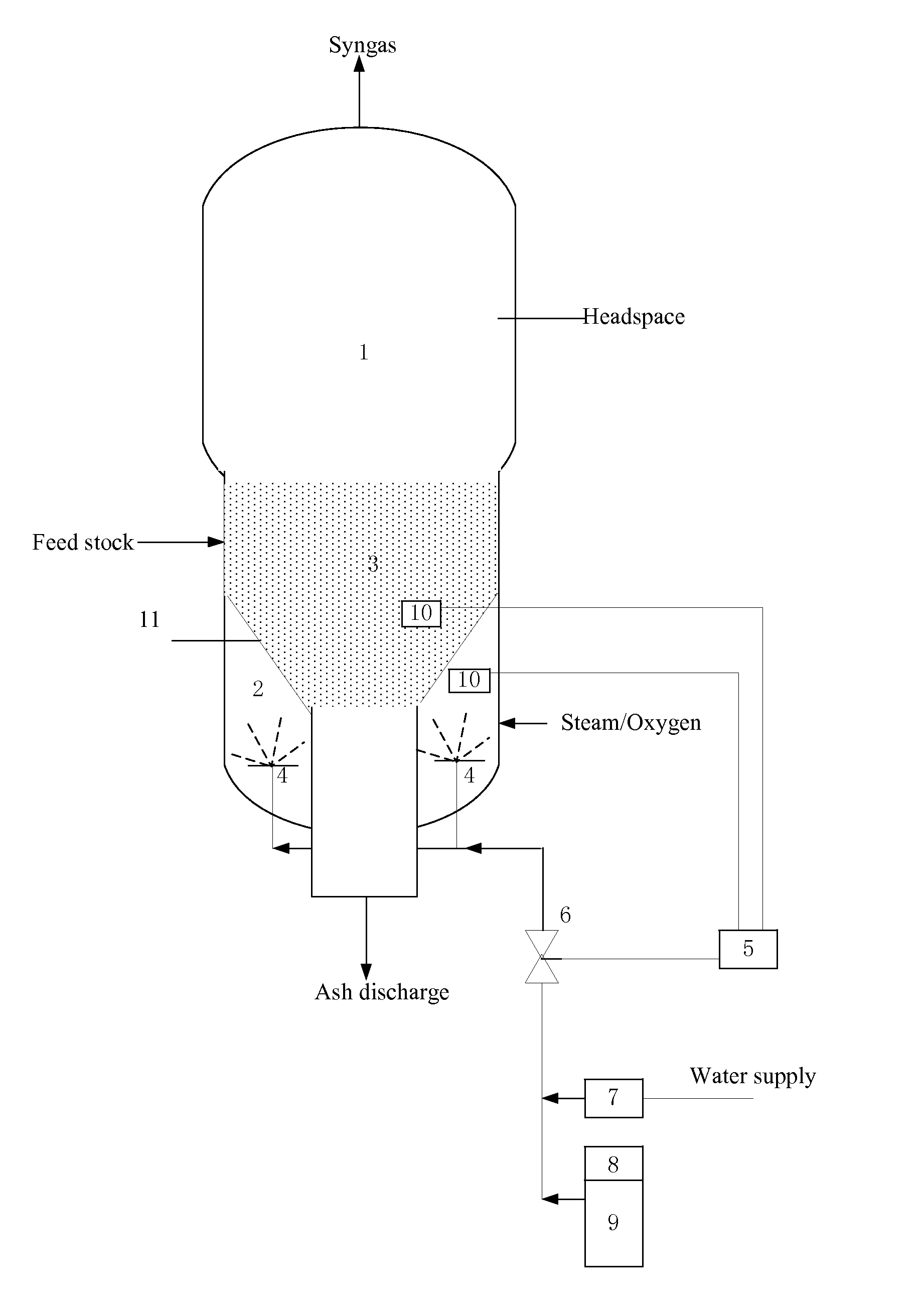
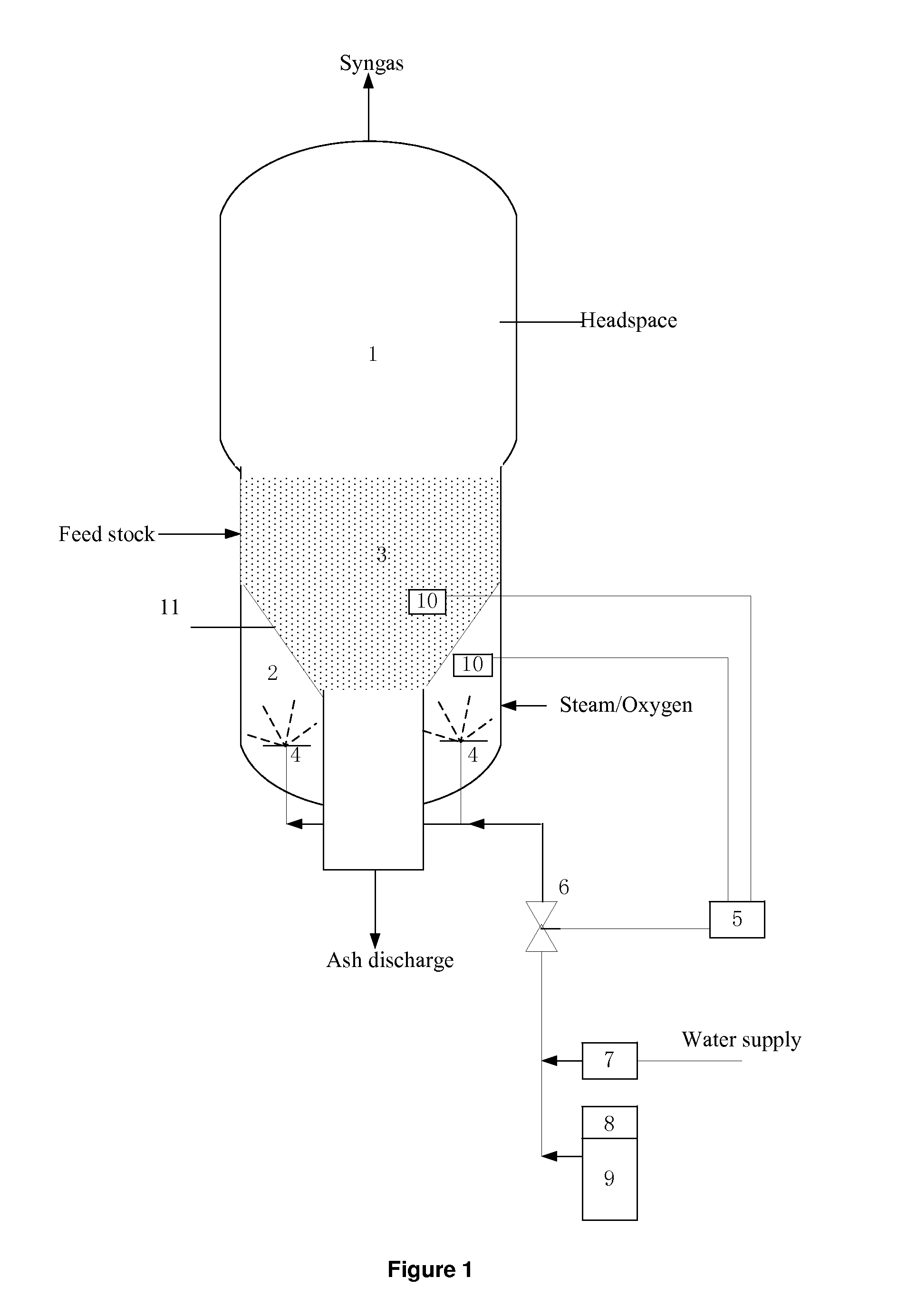
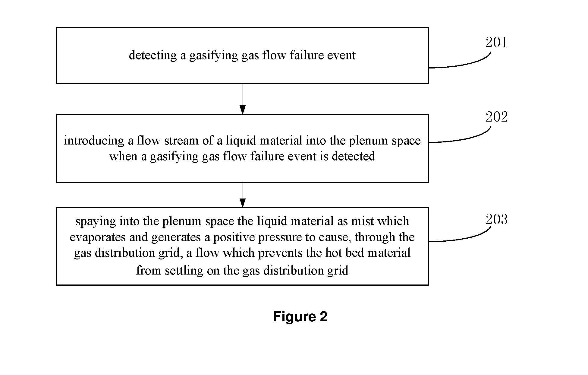
[0036]FIG. 1 schematically illustrates one embodiment of the present invention, showing a gasifier grid of a fluidized bed gasifier and a plenum space 2 underneath. The fluidized bed gasifier comprises a vessel housing a headspace 1 above a fluidized bed 3 of the solid materials being gasified and a gas distribution grid 11 below the bed through which the gasifying gas, such as steam and / or oxygen flow, is introduced to fluidize the feed stock in the gasifier and a plenum space 2 underneath the gas distribution grid 11. An ash discharge pipe is positioned at the bottom of the vessel. Carboneous feed stock such as coal is converted into syngas or synthesis gas primarily containing carbon monoxide (CO) and hydrogen (H2) which is discharged from the top of the vessel.

[0037]The present invention provides a safety system which comprises a water spray mechanism in the plenum place 2. In one embodiment, the apparatus for cooling a gas distribution grid comprises one or more gas flow failur...


PUM


Abstract

An apparatus for cooling a gas distribution grid of fluidized bed gasifier and a method is provided in the present invention. The apparatus comprises a gas flow failure event detector for detecting a gasifying gas flow failure event, a flow control device for controlling the introduction of a flow stream of a liquid material into a spaying device placed in the plenum space of the gasifier, wherein the gas flow failure event detector is in signal connection with the flow control device, and a spaying device for spaying into the plenum space the liquid material as mist which evaporates and generates a positive pressure to cause through the gas distribution grid a flow which prevents the hot bed material from settling on the gas distribution grid.

Description

CROSS-REFERENCE TO RELATED APPLICATIONS[0001]This application claims the benefit of U.S. Provisional Application No. 61 / 803,439, filed Mar. 19, 2013, which is incorporated by reference herein in its entirety.FIELD OF THE INVENTION[0002]The present invention relates to coal gasification using a fluidized bed reactor. More specifically, the invention relates to gasifier grid cooling safety systems and methods to provide safety for the gasifier grid.BACKGROUND OF THE INVENTION[0003]Fluid bed gasifiers for coal and other carboneous materials operate by having an oxygen containing gas pass through a grid into a bed of fluidized solids and the gas reacts with the carbon containing solids to generate syngas. A widely used system is the Synthesis Energy Systems fluidized bed gasifier (“SES gasifier”), described in e.g. U.S. patent application Ser. No. 13 / 532,769. The basic structure of an SES gasifier comprises a vessel housing a headspace above a fluidized bed of the solid materials being ...

Claims


Application Information

Patent Timeline
IPC IPC(8): B01J8/18
CPCB01J8/1836B01J8/44F23C10/20F23N5/242B01J2208/00362B01J8/24
Inventor WINTER, JOHN D.
Owner SYNTHESIS ENERGY SYST
Why Eureka
Try Eureka