Wastewater treatment device

a technology for treating devices and sludge, which is applied in the direction of multi-stage water/sewage treatment, other chemical processes, separation processes, etc., to achieve the effect of enhancing the water recovery rate and suppressing the generation of scales in the desalinization uni

Active Publication Date: 2014-10-23
MITSUBISHI HITACHI POWER SYSTEMS ENVIRONMENTAL SOLUTIONS LTD
View PDF3 Cites 12 Cited by
  • Summary
  • Abstract
  • Description
  • Claims
  • Application Information

AI Technical Summary

Benefits of technology

[0024]According to the invention, since the fluoride ion concentration in the wastewater is reduced, generation of scales in the desalinization unit can be suppressed. As a result, it is possible to enhance the recovery rate of the water in the desalinization unit.

Problems solved by technology

Although the treated water subjected to the purifying treatment is generally discharged into the environment, the treated water obtained by subjecting the industrial wastewater to the purifying treatment is reused for industrial water in places where it is difficult to secure industrial water.

Method used


Image

  • Wastewater treatment device
  • Wastewater treatment device
  • Wastewater treatment device

Examples


first embodiment

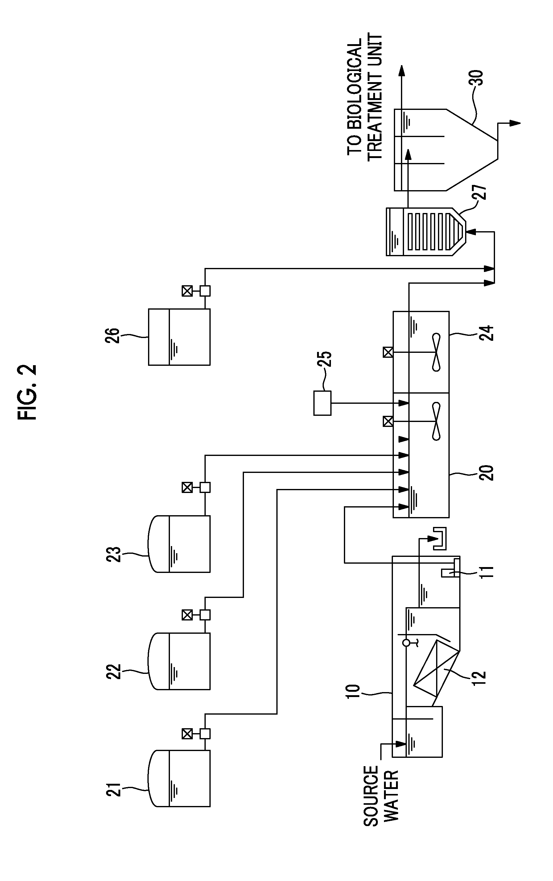
[0044]FIG. 2 is a schematic view of a pretreatment unit of a wastewater treatment device related to a first embodiment.

[0045]An oil separation device 10 of the pretreatment unit of the wastewater treatment device of the first embodiment receives the wastewater (source water) from a plant. In the oil separation device 10, an inclined portion is provided within a tank, and an oil separator 12 is installed at the inclined portion. The oil separator 12 has a configuration in which a plurality of corrugated-plates are arranged. When the source water that has flowed into the oil separation device 10 passes through the oil separator 12, the oil contained in the source water floats on the surface of the water. The oil that floats on the surface of the water is recovered and discharged. The wastewater from which the oil is eliminated is discharged from the oil separation device 10 by a submerged pump 11. In FIG. 2, the submerged pump is installed within the tank (in the wastewater) of the oi...

second embodiment

[0067]FIG. 3 is a schematic view of a pretreatment unit of a wastewater treatment device related to a second embodiment. The pretreatment unit 2 in the wastewater treatment device of the second embodiment is different from that in the wastewater treatment device of the first embodiment in that this pretreatment unit includes a circulation unit 40 that recovers the seed crystals precipitated in the precipitation tank 30 and re-feeds the seed crystals into the reaction vessel 20.

[0068]The circulation unit 40 includes a pump 41 and a cyclone 42.

[0069]The pump 41 discharges a slurry including the seed crystals from the bottom of the precipitation tank 30, and transports the slurry to the cyclone 42.

[0070]The cyclone 42 separates the seed crystals, the flocs (the chelate compounds and the suspended particles) and the sludge from the slurry. In order to facilitate the separation of the seed crystals and the other components, the seed crystals preferably have a size of about 0.03 mm to 1 m...

third embodiment

[0074]FIG. 4 is a schematic view of a wastewater treatment device related to a third embodiment.

[0075]The pretreatment unit of the wastewater treatment device of the third embodiment includes the same oil separation device 50, reaction vessel 60, aging tank 64, and precipitation tank 70 as those of the first embodiment. In the third embodiment, the seed crystal feeding unit and granulation tank of the first embodiment are not installed. A chelate tank 61, a flocculant tank 62, an alkali tank 63, and a polymer tank 66 are connected to the reaction vessel 60.

[0076]In the wastewater treatment device of the third embodiment, a fluoride concentration reduction unit 80 is installed between the pretreatment unit 2 and the biological treatment unit 3. The fluoride concentration reduction unit 80 stores a fluidized bed 81 inside a vessel 82. The seed crystals of the fluidized bed 81 on which the fluoride compounds can be deposited are filled into the vessel into which the wastewater can flow...


PUM

PropertyMeasurementUnit
concentrationaaaaaaaaaa
sizeaaaaaaaaaa

Abstract

Provided is a wastewater treatment device that can reduce the fluoride ion concentration in industrial wastewater to improve the recovery rate of purified water. A wastewater treatment device (1) includes a biological treatment unit (3) that decomposes and eliminates organic matter in wastewater by means of microorganisms, and a desalinization unit (4) that is provided downstream of the biological treatment unit (3) and eliminates salt-forming ionic components from within the wastewater. A pretreatment unit (2), which removes components, such as heavy metals or oil contained in the wastewater, which inhibit the function of the biological treatment unit (3) or the desalinization unit (4), is provided upstream of the biological treatment unit (3), and the pretreatment unit (2) is provided with a fluoride concentration reduction unit that reduces the concentration of fluoride ions in the wastewater by eliminating the fluoride ions from within the wastewater.

Description

TECHNICAL FIELD[0001]The present invention relates to a wastewater treatment device for purifying and treating industrial wastewater in order to reuse the industrial wastewater.BACKGROUND ART[0002]Industrial wastewater from plants is subjected to purifying treatment, such as elimination of heavy metal components, suspended particles, and the like and decomposition and elimination of organic matter by microorganisms. Although the treated water subjected to the purifying treatment is generally discharged into the environment, the treated water obtained by subjecting the industrial wastewater to the purifying treatment is reused for industrial water in places where it is difficult to secure industrial water. In this case, as described in PTL 1, the desalination treatment of eliminating ionic components contained in the wastewater is performed after the heavy metal components, the suspended particles, the organic matter, and the like are eliminated.[0003]In a wastewater treatment device...

Claims


Application Information

Patent Timeline
Patent Type & Authority Applications(United States)
IPC IPC(8): C02F9/00C02F1/70C02F3/00C02F1/52
CPCC02F9/00C02F3/00C02F1/70C02F1/52C02F1/5245C02F3/12C02F2001/5218C02F2101/14C02F1/441C02F3/1273C02F2101/20C02F2101/32C02F2303/24Y02W10/10C02F1/4695C02F3/121
Inventor KAMIMURA, KAZUHIDEISHINO, MAKOTOYOSHIOKA, SHIGERUOTOZAI, HOZUMITERAKURA, SEIICHISUZUKI, HIDEOKONDO, GAKU
Owner MITSUBISHI HITACHI POWER SYSTEMS ENVIRONMENTAL SOLUTIONS LTD
Why Eureka
Try Eureka