Photonic nanoantenna mediated gene circuit reconfiguration

Inactive Publication Date: 2014-11-20
RGT UNIV OF CALIFORNIA
View PDF2 Cites 6 Cited by
  • Summary
  • Abstract
  • Description
  • Claims
  • Application Information

AI Technical Summary

Benefits of technology

[0026]Accordingly, an aspect of the invention is to provide a biomolecular carrier that is precise, predictable, and easy to introduce into a cell.
[0027]Another aspect of the invention is to

Problems solved by technology

However, many gene circuits are incomplete or only partially understood.
The complexity of the system and the specific properties of the components and their pattern of interactions make it difficult to determine how gene-circuit design relates to gene-circuit function in many circuits.
One major challenge is prob

Method used


Image

  • Photonic nanoantenna mediated gene circuit reconfiguration
  • Photonic nanoantenna mediated gene circuit reconfiguration
  • Photonic nanoantenna mediated gene circuit reconfiguration

Examples


Example

Example 1

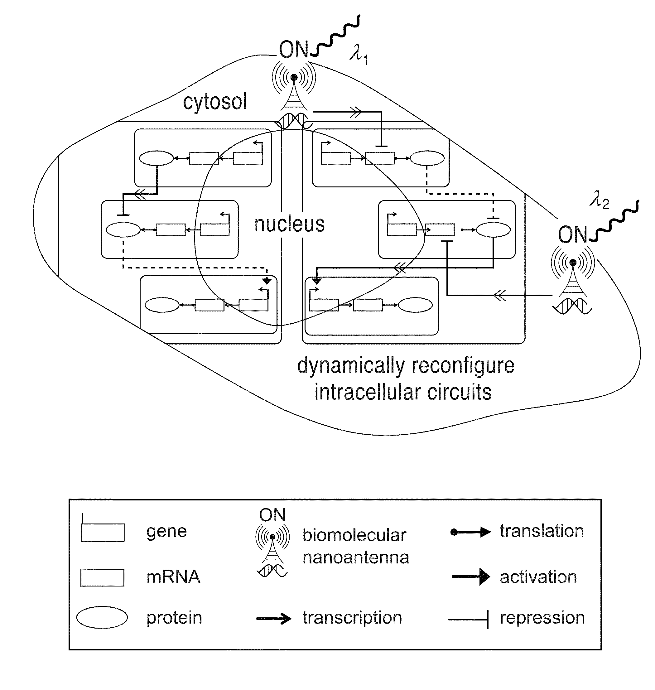
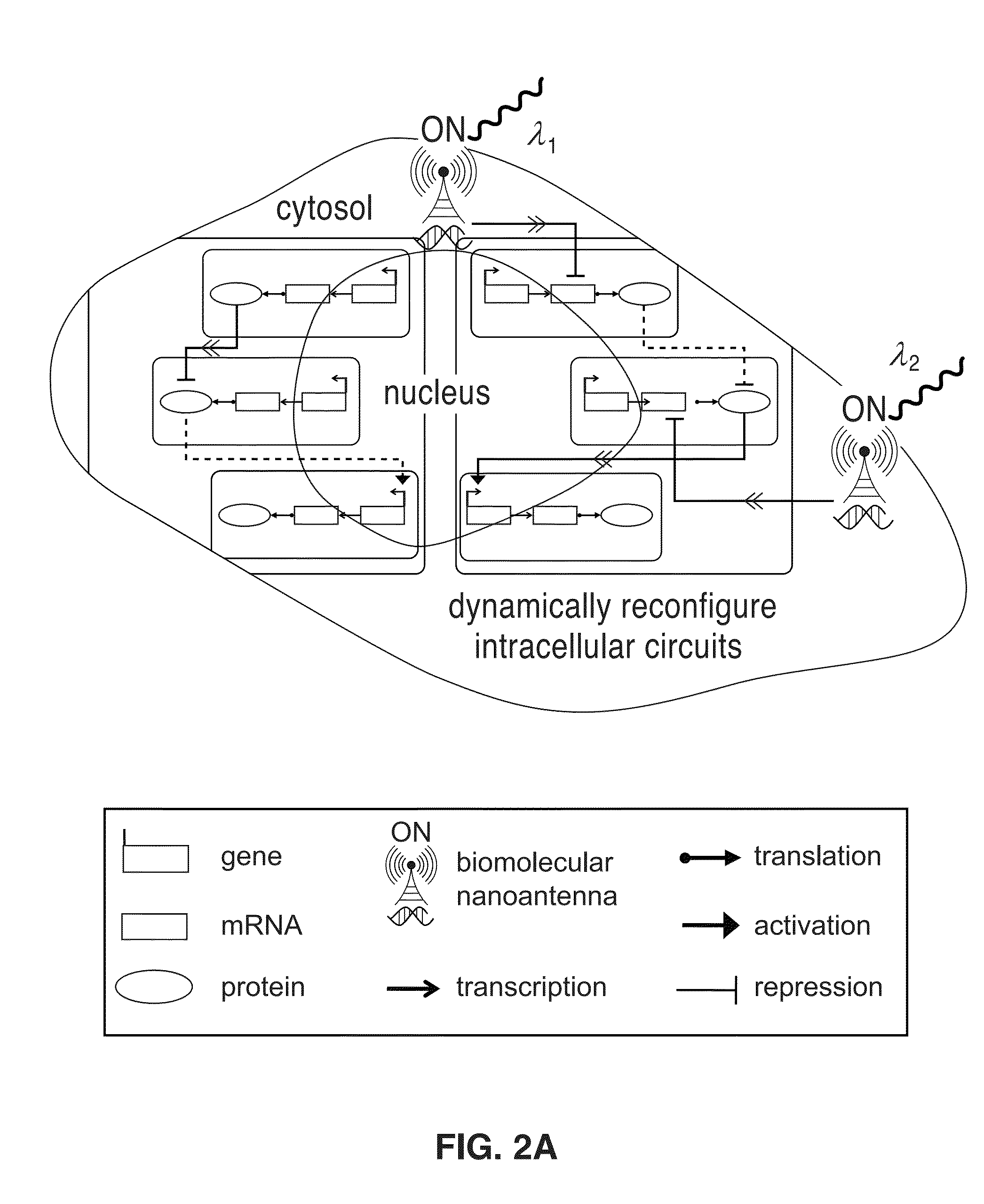
[0058]FIG. 2A through FIG. 2E illustrate a photonic gene circuit according to the invention. As shown in FIG. 2A, dynamic optical circuit reconfiguration is enabled by resonant biomolecular nanoantennas as optical inputs to existing circuit connections of living cells, forming photonic gene circuits. The legend notates symbols and circuit connections.

[0059]In order to demonstrate the functionality of the biomolecular emitter concept, resonant optical nanoantenna carriers were designed such that absorption cross-sections dominate over its scattering cross-sections in order to efficiently convert absorbed optical energy into surface-localized heat.FIG. 2B illustrates conceptually the function of resonant biomolecular nanoantennas function as selectively addressable optical receivers and biomolecular emitters of molecules such as siRNA. The nanoantenna structure is preferably a nanorod made of gold material and on a scale of approximately 50 μm to 60 μm. The electric field may...

Example

Example 2

[0062]Referring now to FIG. 3A and FIG. 3B, an OFF-switch photonic gene circuit according to the invention is illustrated with a p65 biomolecular nanoantenna. Biomolecular nanoantennas were synthesized and experimentally characterized as functional optical receivers and biomolecular emitters of siRNA. Inside living cells, interfering siRNA can be selected that silences intracellular genes in a highly sequence-specific manner, but alone, it lacks the temporal control necessary for precise modulation. Biomolecular nanoantennas combine the benefits of sequence-specificity with spatiotemporal control. Optical silencing of endogenous genes has been successfully demonstrated using interfering oligonucleotides liberated from nanoantennas. Optical gene silencing was used as an optical input signal to interface existing circuit connections of living cells in order to engineer photonic gene circuits.

[0063]The circuit diagram for an OFF-switch photonic gene circuit is shown in FIG. 3A...

Example

Example 3

[0068]FIG. 4A through FIG. 4C illustrate an ON-switch photonic gene circuit according to the invention constructed using a modular OFF-switch sub-circuit with IκB and p65 chosen to represent Y and X, respectively. FIG. 4A shows a circuit diagram for IκB OFF-switch sub-circuit (i); a circuit diagram for non-resonant control (ii); and a circuit diagram for scrambled control (iii). The flow cytometric analysis of IκB OFF-switch sub-circuit in single HeLa cells. HeLa cells immunostained using AF488 labeled anti-IκB were used. Flow cytometric data is expressed as percent change of mean AF488 fluorescence intensity between experiment and reference cells for IκB OFF-switch sub-circuit, non-resonant control, and scrambled control. FIG. 4C shows a logic table for ON-switch photonic gene circuit. In the on-state, p65 translocates to the nucleus (p65nucleus). Immunofluorescence imaging of ON-switch photonic gene circuit in HeLa cells: DIC, anti-p65-AF488 immunostaining of p65, and DAP...


PUM

PropertyMeasurementUnit
Wavelengthaaaaaaaaaa
Adsorption entropyaaaaaaaaaa
Aspect ratioaaaaaaaaaa

Abstract

A selectively addressable optical biomolecular carrier and its method of use for reconfiguring gene circuits are described. One carrier is a plasmon resonant nanoantenna formed from a gold metal nanorod coated with a cationic phospholipid bilayer with an aspect ratio between 2.0 and 8.0 and plasmon resonance wavelength in the near infrared range. Biomolecules such as siRNA adhere to the carrier and are introduced into a cell. The biomolecules are released from the nanoantenna carriers with exposure to light at the plasmon resonance wavelength. The nanoantenna efficiently converts absorbed optical energy to surface localized heat releasing the biomolecules at a time determined by the user. The carrier can be used to modify gene circuits by allowing temporal control over the genes within a selected gene circuit through the optical release of interfering nucleotides. Optical silencing of endogenous genes with siRNA released from nanoantenna carriers was used to illustrate the methods.

Description

CROSS-REFERENCE TO RELATED APPLICATIONS[0001]This application is a 35 U.S.C. §111(a) continuation of PCT international application number PCT / US2012 / 067103 filed on Nov. 29, 2012, incorporated herein by reference in its entirety, which claims priority to, and the benefit of, U.S. provisional patent application Ser. No. 61 / 564,556 filed on Nov. 29, 2011, incorporated herein by reference in its entirety. Priority is claimed to each of the foregoing applications.[0002]The above-referenced PCT international application was published as PCT International Publication No. WO 2013 / 082304 on Jun. 6, 2013, incorporated herein by reference in its entirety.STATEMENT REGARDING FEDERALLY SPONSORED RESEARCH OR DEVELOPMENT[0003]This invention was made with Government support under Grant Number EY018241 awarded by the National Institutes of Health (NIH). The Government has certain rights in the invention.INCORPORATION-BY-REFERENCE OF MATERIAL SUBMITTED ON A COMPACT DISC[0004]Not ApplicableBACKGROUND...

Claims


Application Information

Patent Timeline
IPC IPC(8): C12N13/00
CPCC12N13/00C12N15/111C12N2310/14C12N2320/30C12N2320/32Y10T428/2991
Inventor LEE, LUKE P.LEE, SOMIN EUNICE
Owner RGT UNIV OF CALIFORNIA
Why Eureka
Try Eureka