COMBINED PROCESSES FOR UTILIZING SYNTHESIS GAS with LOW CO2 EMISSION AND HIGH ENERGY OUTPUT

a synthesis gas and gas technology, applied in the direction of gasification process details, gas contaminants removal, inorganic chemistry, etc., can solve the problems of limited supply, limited carbon neutral alternatives to fossil fuels, etc., to achieve the effect of f-t reaction forming diesel or gasoline, and low co2 emission

Active Publication Date: 2014-12-11
QUANTAFUEL AS
View PDF2 Cites 13 Cited by
  • Summary
  • Abstract
  • Description
  • Claims
  • Application Information

AI Technical Summary

Benefits of technology

[0021]The term “comprises/comprising” when used in this specification is taken to specify the presence of stated features, integers, steps or components but does not preclude the presence or addition of one or more other features, integers, steps, components or groups thereof.
[0022]As used herein, the term “neutral” with respect to emitted CO2 means that total carbon emission to the atmosphere neither increases nor reduces during a process. One example of a carbon neutral process is plants assimilating carbon (in the form of CO2) from the atmosphere and storing it in the form of cellulose, sugars, or other biomass and the combustion of the biomass in air to produce the same amount of CO2 as was assimilated by the plants.
[0023]As used herein, “organic waste” refers to all waste containing organic chemicals containing carbon and hydrogen. Examples of organic waste include municipal solid waste, plastics, sewage, animal manure, and hospital waste.
[0024]As used herein “biological waste” refers to any waste of biological origin containing carbon and hydrogen. Examples of biological waste include olive pits, rice husks, bagasse, wood chips, sawdust, corn husks, and products and byproducts of agricultural and/or forestry processes including

Problems solved by technology

Carbon neutral alternatives to fossil fuels, including biodiesel and ethanol are limited by their limited supply, costs of production, and their requirement for farmland that may be needed for food production.
The production of hydrocarbon fuels such as diesel and gasoline are not described, however, and the installation as described is not suitable for F-T reactions forming diesel or gasoline.
The system is designed to minimize the release of toxic

Method used


Image

  • COMBINED PROCESSES FOR UTILIZING SYNTHESIS GAS with LOW CO2 EMISSION AND HIGH ENERGY OUTPUT
  • COMBINED PROCESSES FOR UTILIZING SYNTHESIS GAS with LOW CO2 EMISSION AND HIGH ENERGY OUTPUT

Examples


Embodiment Construction

[0035]Specific embodiments of the invention are described with reference to the accompanying drawings. This invention may, however, be embodied in many different forms and should not be construed as limited to the embodiments set forth herein. Rather, these embodiments are provided so that this disclosure will be thorough and complete, and will fully convey the scope of the invention to those skilled in the art. The terminology used in the detailed description of the embodiments illustrated in the accompanying drawings is not intended to be limiting of the invention. In the drawings, like numbers refer to like elements.

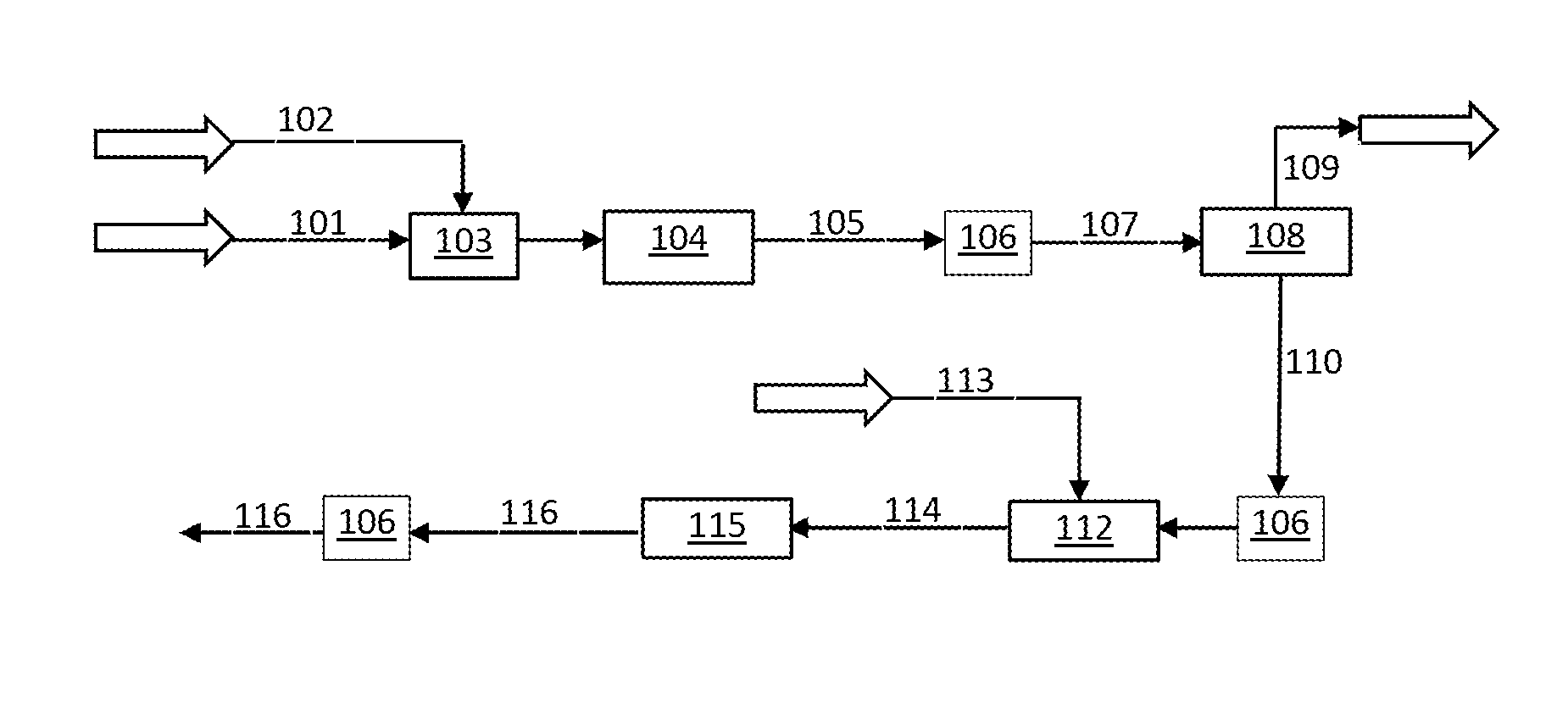
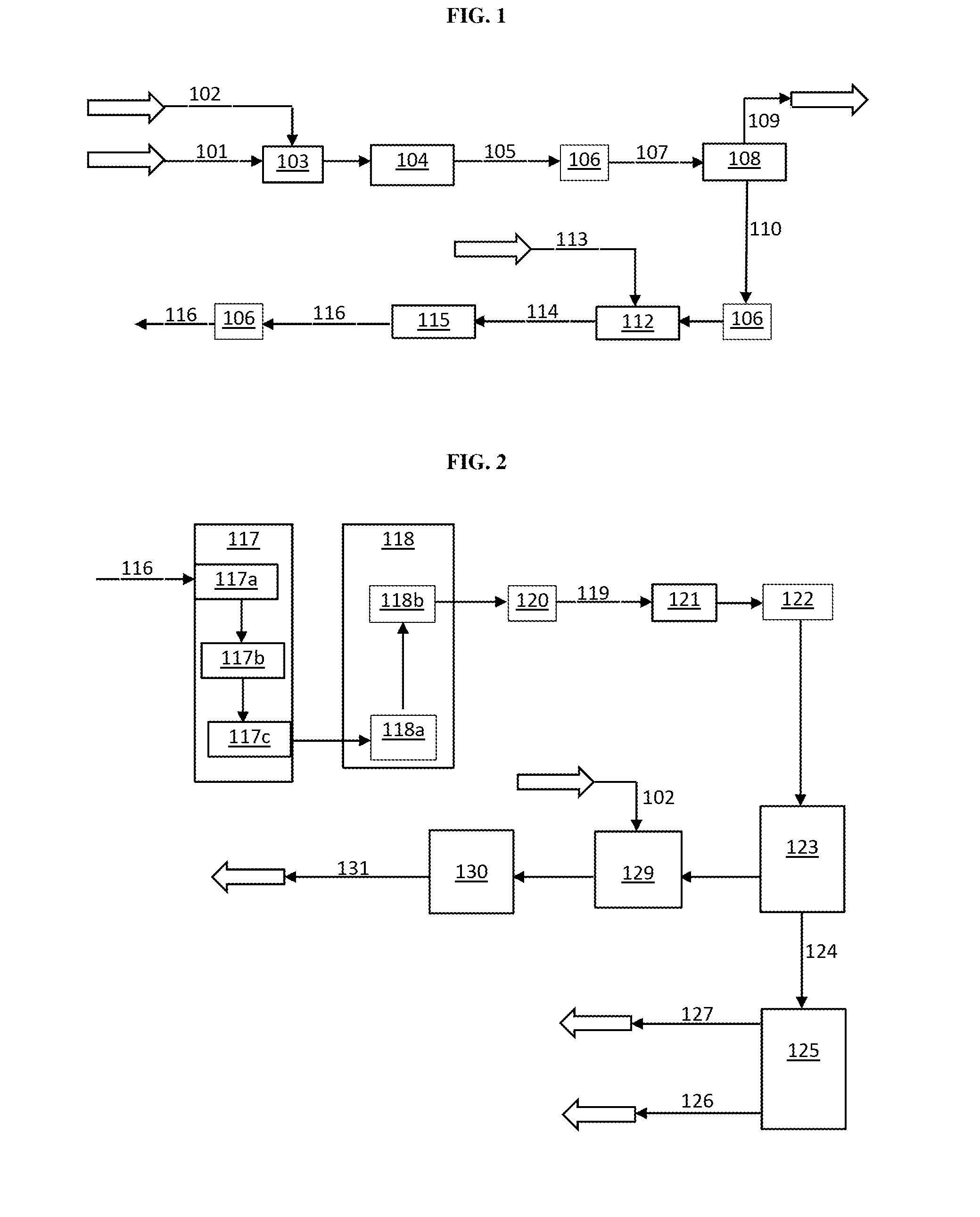
[0036]The following description focuses on an embodiment of the present invention applicable to a process and system for the synthesis of a hydrocarbon fuel and in particular to a process and system for the synthesis of diesel fuel, methane, and / or methanol. However, it will be appreciated that the invention is not limited to this application but may be applied to the...


PUM

PropertyMeasurementUnit
Temperatureaaaaaaaaaa
Percent by massaaaaaaaaaa

Abstract

A process and system for producing liquid and gas fuels and other useful chemicals from carbon containing source materials comprises cool plasma gasification and/or pyrolysis of a source material to produce synthesis gas using the produced synthesis gas for the production of a hydrocarbon, methanol, ammonia, urea, and other products. The process and system are capable of sequestering carbon dioxide and reducing NOx and SOx.

Description

FIELD OF THE INVENTION[0001]The present invention relates generally to the conversion of carbon containing waste materials into useful fuels. More specifically, the invention provides for methods, systems, and apparatus for the conversion of materials containing carbon to diesel and other useful fuels using synthesis gas as an intermediate.BACKGROUND OF THE INVENTION[0002]The reality of global climate change is motivating efforts to reduce the emission of human-produced CO2 and other greenhouse gases into the atmosphere. The combustion of fossil fuels such as coal, gasoline, and diesel is a major source of CO2 emissions and contributes to increasing levels of CO2 in the atmosphere. Carbon neutral alternatives to fossil fuels, including biodiesel and ethanol are limited by their limited supply, costs of production, and their requirement for farmland that may be needed for food production. There remains a need for carbon neutral alternatives to diesel, gasoline, and other fuels produc...

Claims


Application Information

Patent Timeline
IPC IPC(8): C07C1/04C01B3/02
CPCC07C1/0485C01B3/02C07C1/041C01B2203/0255C01B2203/1094C01B2203/062C01B2203/061C01B2203/1052C01B2203/1064C01B2203/0283C10G2/30C10G2/34C10J3/18C10J2300/0916C10J2300/0946C10J2300/0969C10J2300/1238C10J2300/1618C10J2300/1659C10J2300/1662C10J2300/1665C10K1/004C10K3/04Y02E50/10Y02E50/30Y02P20/145Y02P30/40C01B3/16C07C29/152C10L1/02C10L1/04C10L2290/04C10L2290/38C10L2290/42
Inventor SELSTAM, HENRIKFAREID, ERIK
Owner QUANTAFUEL AS
Why Eureka
Try Eureka