Method for making an ordered magnetic alloy

Active Publication Date: 2014-12-18
NATIONAL TSING HUA UNIVERSITY
View PDF2 Cites 106 Cited by
  • Summary
  • Abstract
  • Description
  • Claims
  • Application Information

AI Technical Summary

Benefits of technology

[0014]According to this invention, there is provided a method for making an ordered magnetic alloy that includes: (a) providing a thermally conductive base having opposite first and second surfaces; (b) forming a thermal barrier layer on the first surface of the thermally conductive base; (c) forming a disordered magnetic alloy layer on the thermal barrier layer, the disordered magnetic alloy layer being made from a dis

Problems solved by technology

Conventionally, the ordered phase of the magnetic material can be obtained by subjecting a non-ordered magnetic material to an annealing treatment under a phase-changing temperature higher than 500° C. Since the phase-changing temperature is relatively high, it is problematic to integrate the annealing treatment into an integrated circuit (IC) manufacturing process.
However, sample (A) has a large average grain size and a broad size distribution (about 112±33.6 nm), which is not suitable for making ultrahigh-density perpendicular recording media.
Howev

Method used


Image

  • Method for making an ordered magnetic alloy
  • Method for making an ordered magnetic alloy
  • Method for making an ordered magnetic alloy

Examples


example 1 (

E1)

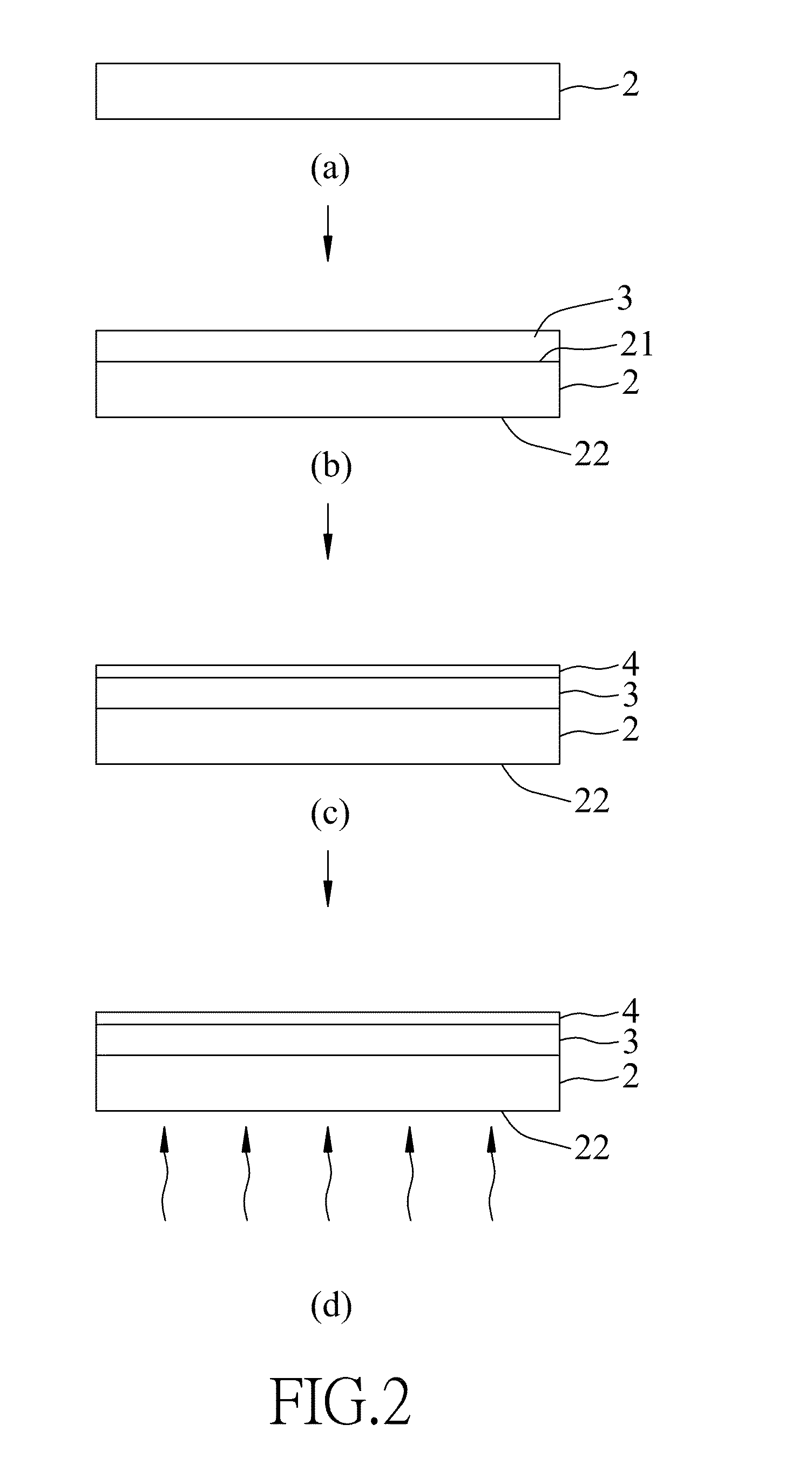
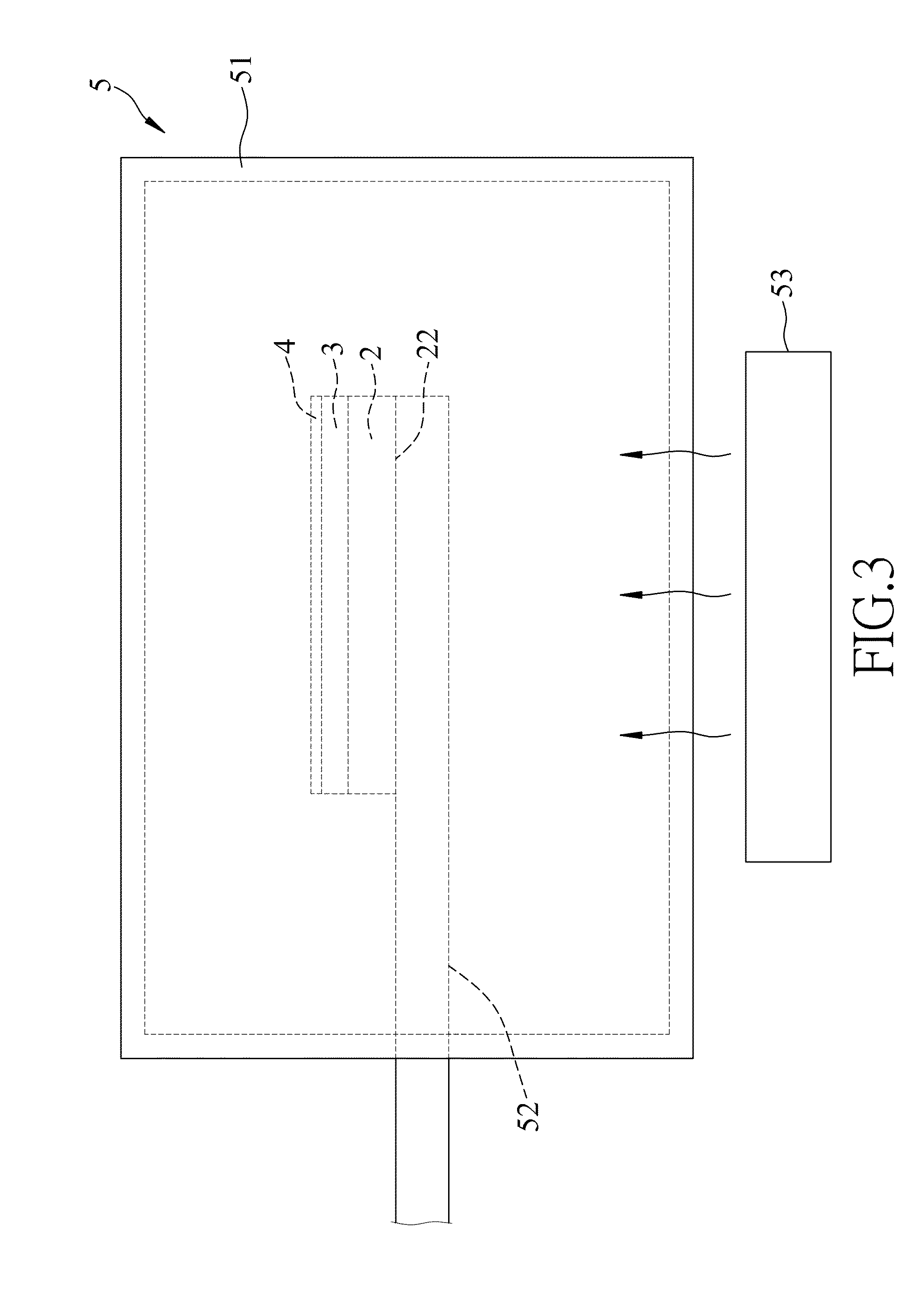
[0041]A silicon substrate having a thickness of 450 μm was provided as the thermally conductive base 2. A 30 nm SiO2 layer was deposited on the silicon substrate as the thermal barrier layer 3 by sputtering techniques. A total thickness of 5 nm of a FePt alloy layer (including a sub-layer of Fe and a sub-layer of Pt) was deposited on the SiO2 layer as the disordered magnetic alloy layer 4 by co-sputtering techniques (or planetary sputtering techniques) so as to form a stack of the thermally conductive base 2, the thermal barrier layer 3 and the disordered magnetic alloy layer 4. The stack was placed on a quartz stage 52 in the vacuum quartz tube 51 of the heating system 5 (see FIG. 3) which was operated under a pressure of 1×10⁻⁵ torr. The second surface 22 of the thermally conductive base 2 was directly irradiated by a light having a wavelength ranging from 400 nm-1100 nm and generated from the near-infrared light source 53, such that the thermally conductive base 2 was heated f...

examples 2 to 4 (

EX2 to EX4)

[0042]The conditions of preparing the ordered magnetic alloy (ordered FePt alloy) of each of Examples 2 to 4 (EX2 to EX4) of the present invention were similar to those of Example 1 (E1), except that the heating rates of EX2 to EX4 were 20, 25, and 40° C. / sec, respectively.

[0043]FIG. 4 shows the XRD patterns of the ordered FePt alloys of EX3 and EX4, each having diffraction peaks of [001] orientation and [002] orientation of L10-FePt.

[0044]Referring to FIG. 5, the volume fractions of L10 domains of the ordered FePt alloys of EX1 to Ex4 are respectively 0.66, 0.79, 0.88 and 0.9.

[0045]FIGS. 6(a) and 6(b) show the hysteresis loops of the out-of-plane coercivity (Hc⊥) and the in-plane coercive field (Hc / / ) for the ordered FePt alloys of EX3 and EX4, respectively. A comparison in the out-of-plane coercivity (Hc⊥) between Ex3 and Ex4 shows that the out-of-plane coercivity (Hc) is increased by increasing the heating rate. As shown in FIG. 6(b), the shape of the in-plane coercive...

examples 5 to 8 (

EX5 to EX8)

[0046]The conditions of preparing the stacks of Examples 5 to 8 (EX5 to EX8) of the present invention were similar to those of EX4, except that the thicknesses of the thermal barrier layers 3 of EX5 to EX8 were 10, 60, 100, and 200 nm, respectively.

[0047]As shown in FIG. 8 and Table 2, the volume fraction of L10 domains of the ordered FePt alloy is increased from 0.885 (EX5) to 0.960 (EX8) by increasing the thickness of the thermal barrier layer 3 (SiO2) from 10 nm to 200 nm.

TABLE 2ThicknessThermallyThermalDisorderedTransient heatVolumeconductivebarrier layermagneticRatefraction ofHc—Hc / / EXbase Si(μm)SiO2(nm)alloy layera° C. / sTa ° C.L10 domainskOekOe5450.010FePt404000.8856.31.04450.030FePt404000.9008.60.66450.060FePt404000.91010.10.67450.0100FePt404000.93013.60.68450.0200FePt404000.96019.00.5aChemical compositions of the disordered FePt alloy of each Example is Fe55Pt45 (determined by inductively coupled plasma-mass spectrometry).

[0048]As shown in FIG. 9, the ratio of the...


PUM

PropertyMeasurementUnit
Lengthaaaaaaaaaa
Thicknessaaaaaaaaaa
Thicknessaaaaaaaaaa

Abstract

A method for making an ordered magnetic alloy includes (a) providing a thermally conductive base having opposite first and second surfaces; (b) forming a thermal barrier layer on the first surface of the thermally conductive base; (c) forming a disordered magnetic alloy layer on the thermal barrier layer, the disordered magnetic alloy layer being made from a disordered alloy which contains a first metal selected from Fe, Co, and Ni, and a second metal selected from Pt and Pd; and (d) after step (c), applying a transient heat to the thermally conductive base to cause rapid thermal expansion of the thermally conductive base, which, in turn, causes generation of an in-plane tensile stress in the disordered magnetic alloy layer.

Description

CROSS-REFERENCE TO RELATED APPLICATIONS[0001]This application claims priority of Taiwanese Patent Application No. 102121345, filed on Jun. 17, 2013.BACKGROUND OF THE INVENTION[0002]1. Field of the Invention[0003]This invention relates to a method for making an ordered magnetic alloy, more particularly to a method for making an ordered magnetic alloy including applying a transient heat to a thermally conductive base to cause generation of an in-plane tensile stress in a disordered magnetic alloy layer to thereby order the disordered magnetic alloy layer.[0004]2. Description of the Related Art[0005]A magnetic material, such as FePt alloy or CoPt alloy, can be used for making a high storage density perpendicular magnetic recording medium. In order to achieve high thermal stability for the high storage density perpendicular magnetic recording medium, the magnetic material is required to have a high magnetocrystalline anisotropy energy (Ku), a high out-of-plane coercive field (Hc⊥) and a...

Claims


Application Information

Patent Timeline
IPC IPC(8): G11B5/84
CPCG11B5/84C21D2201/00C21D2251/02G11B5/8404C21D1/26H01F10/123H01F10/30H01F41/22
Inventor LAI, CHIH-HUANGWANG, LIANG-WEIWU, YUN-CHUNGSHIH, WEN-CHIEH
Owner NATIONAL TSING HUA UNIVERSITY
Why Eureka
Try Eureka