Process for Preparing Graphene on a SiC Substrate Based on Metal Film-Assisted Annealing

a metal film and substrate technology, applied in the field of microelectronics, can solve the problems of loss of many characteristics of the graphene monolayer, high cost of monocrystal sic thermal decomposition, and low porosity, and achieve simple and energy-saving process. , the effect of low porosity

Active Publication Date: 2014-12-18
XIDIAN UNIV
View PDF5 Cites 301 Cited by
  • Summary
  • Abstract
  • Description
  • Claims
  • Application Information

AI Technical Summary

Benefits of technology

[0016]1. The process for preparing graphene according to the present invention provides a simply and energy-efficient process.
[0017]2. Attributed to the reaction between SiC and CCl4, the double-layered carbon film as formed in the present invention has a smooth surface and low porosity, and the graphene obtained therefrom can be used in gas sealing and liquid sealing.
[0018]3. It is on the metal fil

Problems solved by technology

However, the biggest disadvantage of this method is that the strong interaction between the graphene flakes and the substrate leads to a loss of many characteristics of the graphene monolayer, and weakens the continuity of the graphene.
However, the monocrystal SiC used in the SiC thermal decomposition is very expensive

Method used


Image

  • Process for Preparing Graphene on a SiC Substrate Based on Metal Film-Assisted Annealing
  • Process for Preparing Graphene on a SiC Substrate Based on Metal Film-Assisted Annealing
  • Process for Preparing Graphene on a SiC Substrate Based on Metal Film-Assisted Annealing

Examples


example 1

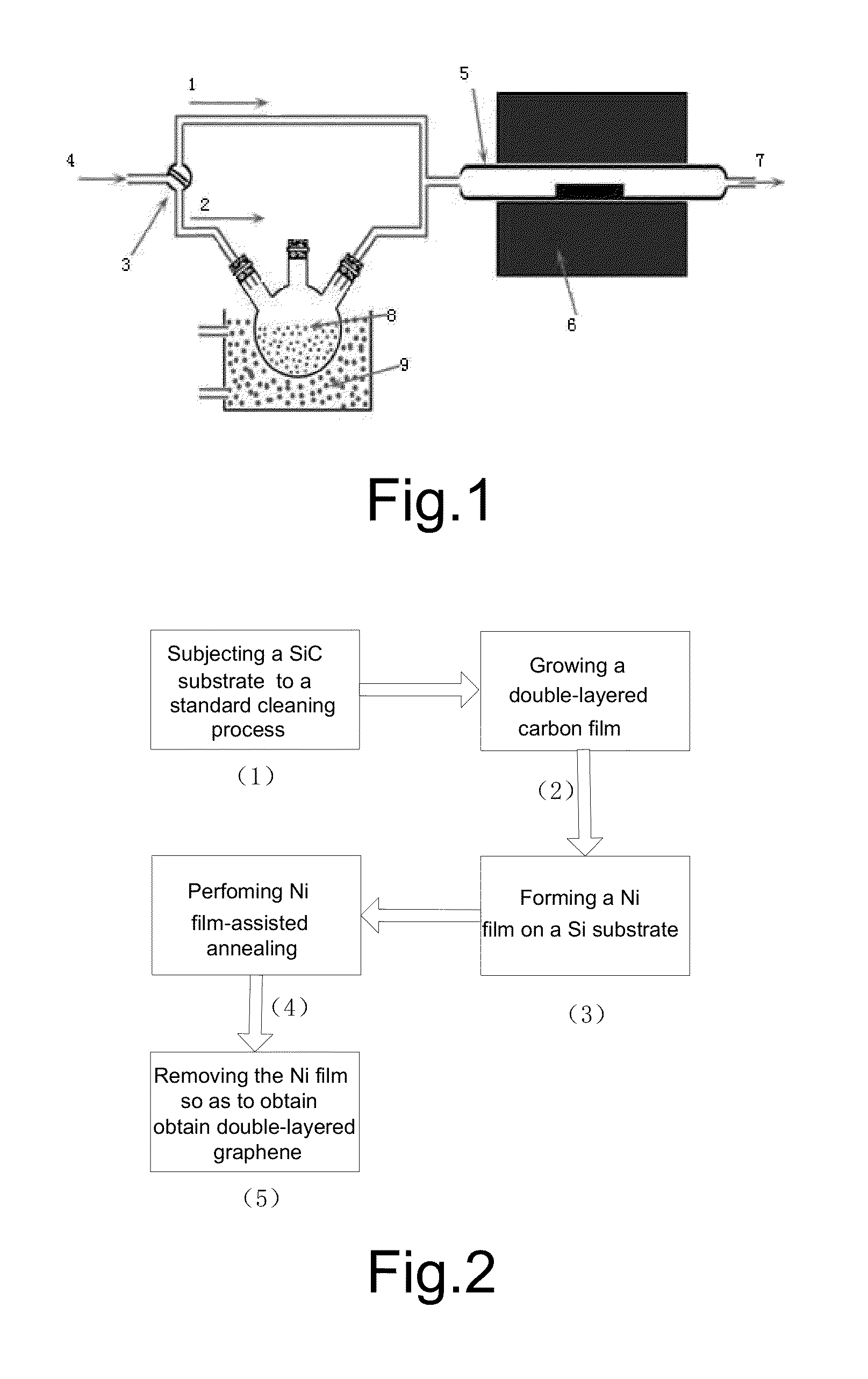
[0042]Step 1: a 6H-SiC substrate was cleaned so as to remove contaminants from its surface.

[0043](1.1) the 6H-SiC substrate sample was immersed in NH4OH+H2O2 for 10 minutes, taken out and dried so as to remove organic residues from the surface of the sample; and

[0044](1.2) the 6H-SiC substrate sample was then immersed in HCl+H2O2 for 10 minutes, taken out and dried so as to remove ionic contaminants.

[0045]Step 2: a quartz tube was loaded with the cleaned 6H-SiC substrate, degassed and heated.

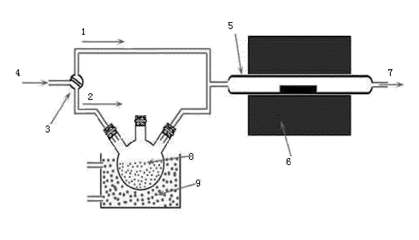
[0046](2.1) the cleaned 6H-SiC was placed into the quartz tube 5, and the quartz tube 5 was placed into the resistance furnace 6;

[0047](2.2) the air tightness of the whole preparation device was checked, then Ar gas was introduced from the gas inlet 4 at a flow rate of 80 ml / min, while controlling Ar gas to enter into the quartz tube through the first channel 1 by the three-way valve 3, and the quartz tube was degassed for 30 minutes so as to discharge the air inside the quartz tube from the gas...

example 3

[0065]Step A: the surface of a 6H-SiC substrate was cleaned by firstly immersing the substrate sample in NH4OH+H2O2 for 10 minutes, taking it out and drying it so as to remove organic residues from the surface of the substrate sample substrate; and then immersing the sample in HCl+H2O2 for 10 minutes, taking it out and drying it so as to remove ionic contaminants.

[0066]Step B: the cleaned 6H-SiC was placed into the quartz tube 5, and the quartz tube was placed into the resistance furnace 6; the air tightness of the whole preparation device was checked, then Ar gas was introduced from the gas inlet 4 at a flow rate of 80 ml / min, while controlling Ar gas to enter into the quartz tube through the first channel 1 by the three-way valve 3, and the quartz tube was degassed for 30 minutes so as to discharge the air inside the quartz tube from the gas outlet 7; and the power of the resistance furnace 6 was turned on to elevate the temperature of the quartz tube to 1150° C.

[0067]Step C: the ...


PUM

PropertyMeasurementUnit
Lengthaaaaaaaaaa
Pressureaaaaaaaaaa
Flow rateaaaaaaaaaa

Abstract

Provided is a process for preparing graphene on a SiC substrate, based on metal film-assisted annealing, comprising the following steps: subjecting a SiC substrate to a standard cleaning process; placing the cleaned SiC substrate into a quartz tube and heating the quartz tube up to a temperature of 750 to 1150° C.; introducing CCl4vapor into the quartz tube to react with SiC for a period of 20 to 100 minutes so as to generate a double-layered carbon film, wherein the CCl4 vapor is carried by Ar gas; forming a metal film with a thickness of 350 to 600 nm on a Si substrate by electron beam deposition; placing the obtained double-layered carbon film sample onto the metal film; subsequently annealing them in an Ar atmosphere at a temperature of 900 to 1100° C. for 10-30 minutes so as to reconstitute the double-layered carbon film into double-layered graphene; and removing the metal film from the double-layered graphene, thereby obtaining double-layered graphene. Also provided is double-layered graphene prepared by said process.

Description

FIELD OF THE INVENTION[0001]The present invention belongs to the field of microelectronics, and relates to semiconductor films and their preparation methods. Specifically, the present invention relates to a process for preparing graphene on a SiC substrate based on metal film-assisted annealing.BACKGROUND[0002]It was in 2004 that graphene first appeared in the laboratory, when scientists Andre Geim and Kostya Novoselov at the University of Manchester discovered that they could get a graphite flake which became thinner and thinner by a very simple method. They isolated a graphite flake from graphite, then stuck both sides of the flake to a special tape and peeled the tapes off, thereby cleaving the graphite flake into two parts. As they repeated this process several times, the flakes got thinner and thinner. Finally, they obtained a monolayer of carbon, which is known as graphene. From then on, numerous new methods have been explored to prepare graphene, among which the following two...

Claims


Application Information

Patent Timeline
IPC IPC(8): H01L21/02H01L29/16
CPCH01L21/02614H01L21/02527H01L29/1606H01L21/02661H01L21/02664H01L21/02378C23C16/26C23C16/01C23C16/0281B82Y30/00B82Y40/00C01B2204/04C01B32/184C30B25/02C23C14/0605
Inventor GUO, HUIZHANG, KEJIZHANG, YUMINGDENG, PENGFEILEI, TIANMIN
Owner XIDIAN UNIV
Why Eureka
Try Eureka