High heat resistance composite separator for lithium secondary battery and lithium secondary battery including same

Active Publication Date: 2014-12-18
SOLAREDGE TECH KOREA LTD CO
View PDF4 Cites 43 Cited by
  • Summary
  • Abstract
  • Description
  • Claims
  • Application Information

AI Technical Summary

Benefits of technology

[0034]According to one aspect of the present disclosure, there is provided a high heat resistance composite separator with superior safety, in which heat shrinkage at high temperature is suppressed due to heat resistance characteristics and a high mechanical strength by coating inorganic particles on one surface of a porous substrate, and heat shrinkage at high temperature is suppressed and a shape change caused by external penetration is prevented by coating a high heat

Problems solved by technology

When used in the melting temperature range of polyethylene or polypropylene, if the temperature of the battery continues to increase by internal/external factors even subsequent to shut-down, the separator melts and loses its shape, which causes a short circuit of electrodes, getting into a dangerous situation.
However, this art involves coating with an inorganic matter which increases in the separator weight and consequently the overall battery weight, causing a reduction in energy density.
Also, because inorganic fillers vulnerable to reaction with a majority of carbonate are used, CO2 gas and other gases are generated by decomposition of a carbonate-based solvent being commonly used, and when left unused for a long time, a bulging phenomenon of a cell is observed, hence there is a limitation in improving battery stability.
However, this also has a factor hindering stability because gas is generated

Method used


Image

  • High heat resistance composite separator for lithium secondary battery and lithium secondary battery including same
  • High heat resistance composite separator for lithium secondary battery and lithium secondary battery including same
  • High heat resistance composite separator for lithium secondary battery and lithium secondary battery including same

Examples


embodiment example 1

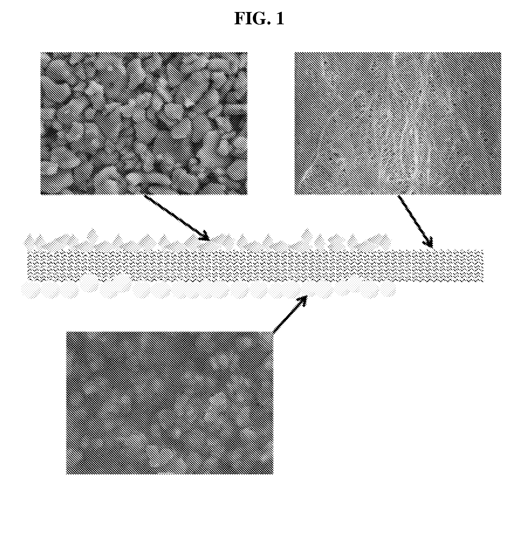
[0126]A composition for an inorganic coating layer was prepared by blending 35 parts by weight of Al2O3, 5 parts by weight of poly(vinylidene fluoride-co-hexafluoropropylene) (PVdF-HFP), and 60 parts by weight of acetone. The prepared composition was coated on one surface of a polyethylene (PE) porous substrate (thickness 16 μm, porosity 47%, air permeability 150.2 sec / 100 ml, W-able) at a coating thickness of about 3 μm by a roller coating process with a slip belt speed of about 10M / hr and a drying temperature of 80° C.

[0127]A composition for a high heat resistance polymer coating layer was prepared by blending 45 parts by weight of meta-type aromatic polyamide (poly(meta-phenylene isophtalamide)), 10 parts by weight of MgO, and 45 parts by weight of N,N-Dimethylacetamide. The prepared composition for the high heat resistance polymer coating layer was sprayed with a roller onto the opposite surface of the porous substrate to the surface coated with the inorganic particles, and cast...

embodiment example 2-1

[0132]As a cathode active material, LiNi(1-x-y)MnxCoyO2 was used and as an anode active material, MGP (China Steel Chemical Corporation) was used, an inorganic coating layer was disposed facing a cathode electrode and a high heat resistance polymer coating layer was disposed facing an anode electrode with the composite separator manufactured in Embodiment example 1 therebetween, and then an aluminum case was applied thereto, to fabricate a lithium secondary battery. A standard size of the battery was 100 mm (thickness)×216 mm (width)×216 mm (length), and a design capacity was 40 Ah.

embodiment example 2-2

[0133]A lithium secondary battery was fabricated by the same method as Embodiment example 2-1, except that a high heat resistance polymer coating layer was disposed facing a cathode electrode and an inorganic coating layer was disposed facing an anode electrode with the composite separator manufactured in Embodiment example 1 interposed therebetween.


PUM


Abstract

Disclosed is a high heat resistance composite separator including a porous substrate having a plurality of pores, an inorganic coating layer formed on one surface of the porous substrate, the inorganic coating layer including a plurality of inorganic particles and a binder polymer disposed on a portion or all of surfaces of the inorganic particles to connect and bind the inorganic particles, and a high heat resistance polymer coating layer formed on the other surface of the porous substrate, the high heat resistance polymer coating layer including a high heat resistance polymer and inorganic particles dispersed in the high heat resistance polymer.

Description

TECHNICAL FIELD[0001]The present disclosure relates to a high heat resistance composite separator for a lithium secondary battery and a lithium secondary battery including the same. More particularly, the present disclosure relates to a composite separator that has superior shape stability at high temperature and a high mechanical strength as well as a shut-down function, and a lithium secondary battery including the same.[0002]The present application claims priority to Korean Patent Application No. 10-2011-0133354 filed in the Republic of Korea on Dec. 13, 2011, the disclosures of which are incorporated herein by reference.BACKGROUND ART[0003]With the rapid development of electronic, communication and computer industries, mobile electronic communication equipments, such as, for example, camcorders, mobile phones, laptop computers, and the like, have been advancing remarkably. Accordingly, the demand for lithium secondary batteries as a power source of mobile electronic communicatio...

Claims


Application Information

Patent Timeline
IPC IPC(8): H01M2/16H01M10/42H01M50/414H01M50/429H01M50/434H01M50/451H01M50/457H01M50/489H01M50/491
CPCH01M2/1686H01M2/1646H01M2/162H01M10/4235H01M10/052H01M50/44H01M50/446H01M50/451H01M50/491H01M50/429H01M50/489H01M50/414H01M50/434H01M50/457Y02E60/10H01M50/449H01M50/417H01M50/431Y02T10/70
Inventor HONG, JI-JUNKO, SUNG-TAEHEO, YOON-JEONGKWON, YOO-JUNG
Owner SOLAREDGE TECH KOREA LTD CO
Why Eureka
Try Eureka