Moving coil miniature loudspeaker module

a loudspeaker module and moving coil technology, applied in the direction of loudspeakers, electrical transducers, cabinet/cabinet/supports, etc., can solve the problems of high intensity broad band electro-magnetic radiation, severe geometric constraints on the components of such compact and light-weight mobile devices, affecting the quality of sound reproduction, etc., to facilitate easy integration in a mobile device, reduce the number of required components, and low power consumption

Active Publication Date: 2015-01-01
ANALOG DEVICES INT UNLTD
View PDF17 Cites 14 Cited by
  • Summary
  • Abstract
  • Description
  • Claims
  • Application Information

AI Technical Summary

Benefits of technology

[0011]By integrating the output amplifier electronics within the perimeter of the frame of the miniature loudspeaker, the length of leads between the output amplifier and the voice coil driven by it is brought to a minimum. As a consequence, noise, stemming from electromagnetic radiation at RF-frequencies that are demodulated into the audio-band and picked up by the signal path between output amplifier and voice coil, is greatly reduced and loudspeaker performance is improved. Furthermore, this design overcomes the need for additional signal filtering components in the signal path between the output amplifier and the voice coil. This considerably simplifies the integration of the miniature module in a host circuit, reducing the cost of the host device. Furthermore, such additional signal filtering components may add to the impedance of the loudspeaker with a contribution that may be comparable to the impedance of the voice coil itself. An increased impedance load in the signal path deteriorates the sensitivity of the loudspeaker. By avoiding additional signal filtering components the sensitivity of the loudspeaker module is improved, and consequently the performance of the host device comprising the loudspeaker module is enhanced.
[0032]By reducing the length of the signal path to a minimum, the amount of emitted electromagnetic radiation stemming from the class-D output amplifier is greatly reduced. In addition to the above-mentioned advantages of reduced pick-up of demodulated RF-frequencies affecting the signal in the audio-range, the reduced signal path therefore also significantly reduces electromagnetic interference in the MHz-range with other components of the host device, such as the antenna of a mobile device.

Problems solved by technology

Components for use in such compact and light-weight mobile devices are therefore subject to severe geometric constraints.
Due to the compact design of the mobile devices, this results in a high intensity broad band electro-magnetic radiation.
Owing to the highly compact miniaturized design, planar miniature loudspeakers are typically susceptible to parasitic electromagnetic radiation emitted in the vicinity as electromagnetic interference (EMI), which may be picked up by the voice coil, or other electrical wiring of the miniature loudspeaker, as noise signal affecting the quality of sound reproduction.
Further due to the miniaturized design, the miniature loudspeaker is susceptible to harmonic distortion, e.g. due to external load on the mechanical system of the loudspeaker, which again may affect the quality of sound reproduction.
While many electronic devices are suited for surface mounting, miniature loudspeakers are commonly not compatible with such a mounting process, since the heat typically applied during the manufacturing process would affect the permanent magnetic structure included in the speaker.
In addition, when mounting the miniature loudspeaker on a main PCB, additional constraints of appropriate vibration-control in the connection between the loudspeaker and the main PCB apply, due to the very nature of the loudspeaker as a sound-pressure / vibration generating device.

Method used


Image

  • Moving coil miniature loudspeaker module
  • Moving coil miniature loudspeaker module
  • Moving coil miniature loudspeaker module

Examples


Embodiment Construction

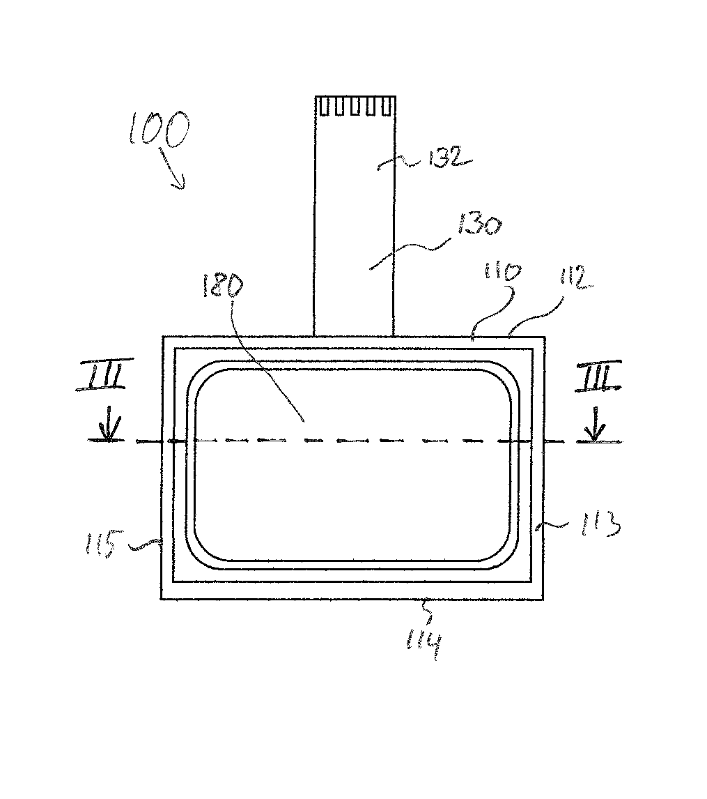
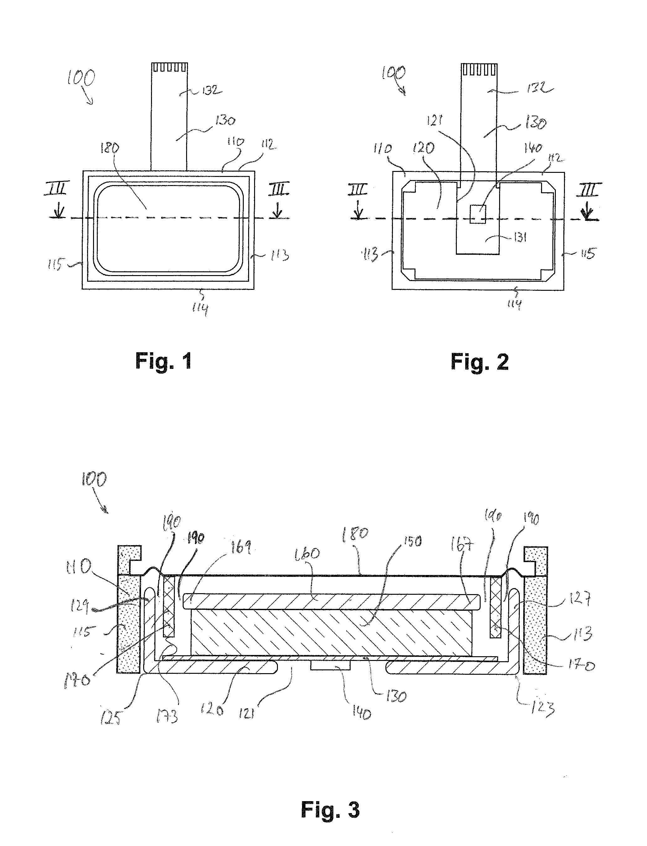
[0042]Referring to FIGS. 1-4, a moving coil miniature loudspeaker 100 comprises a static part with a frame 110 defining a principal plane of the miniature loud-speaker 100. The frame 110 has peripheral walls 112, 113, 114, 115 defining a lateral perimeter.

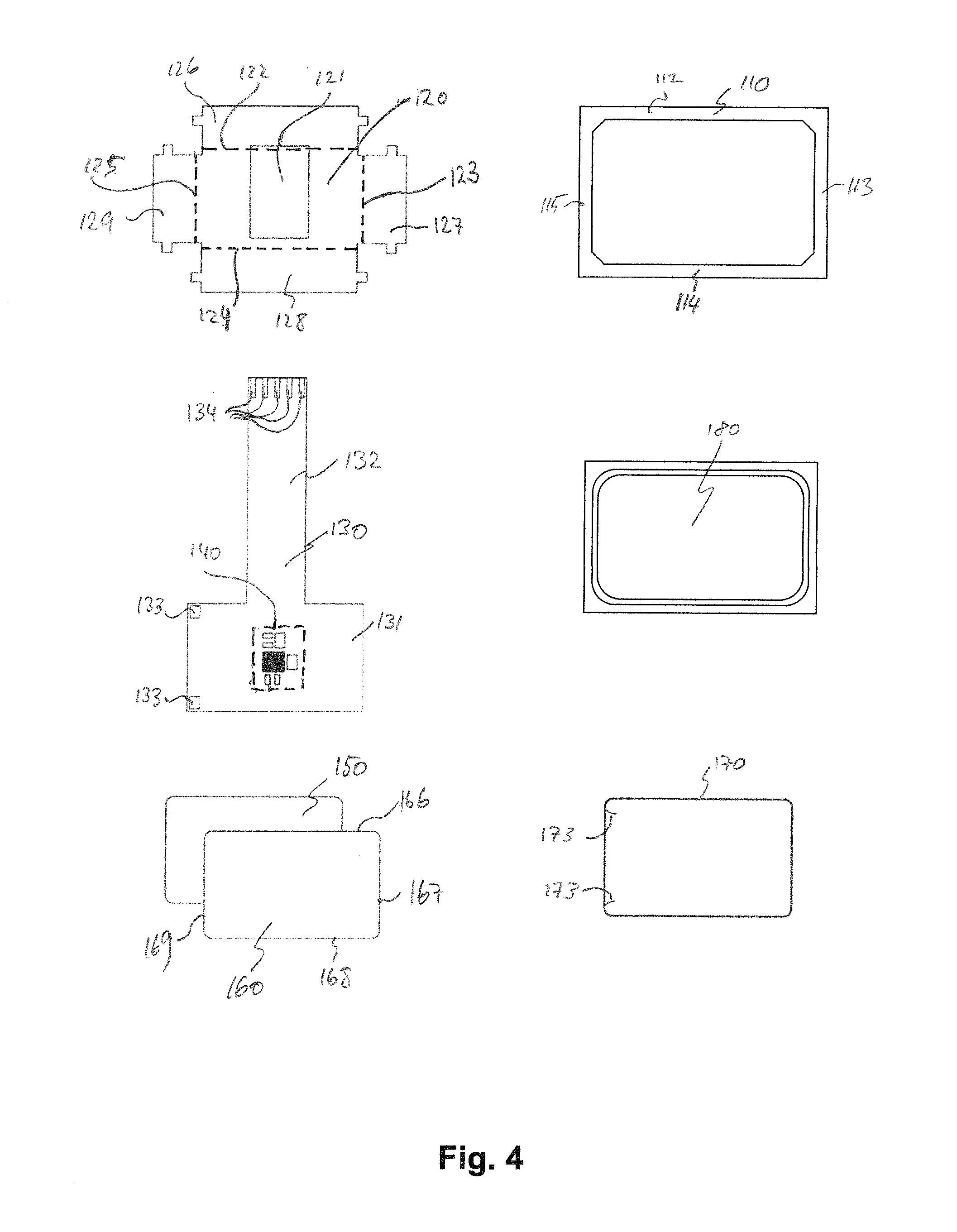
[0043]A magnetic circuit is arranged within the perimeter of the frame 110 and rigidly attached to the frame 110. The magnetic circuit comprises a planar slab-shaped permanent magnet 150 sandwiched between two planar slab-shaped pole pieces 120, 160 of magnetically conducting material, and an air gap 190. The slab-shaped permanent magnet 150 and the slab-shaped pole pieces 120,160 are arranged parallel to the principal plane. The upper pole piece 160 is located between the permanent magnet 150 and a diaphragm 180 at the top of the miniature loudspeaker 100; and the lower pole piece 120 is located on an opposite side of the permanent magnet 150 at the bottom of the miniature loud speaker 100. The moving coil miniature loudspeaker 10...


PUM


Abstract

A miniature loudspeaker may include a driver module with a flexible carrier having a proximal portion arranged within the perimeter of the frame and a distal portion arranged outside the perimeter of the frame, the flexible carrier carrying an output amplifier. The flexible carrier may be provided with electrically conductive traces connecting an amplifier input with input contact pads placed on the distal portion. The flexible carrier may be provided with electrically conductive traces connecting an amplifier output with output contact pads placed at the proximal portion. The output amplifier may be arranged on the proximal portion of the flexible carrier within the perimeter of the frame. The proximal portion of the flexible carrier may be rigidly attached to the static part. The output contact pads may be connected with the voice coil through flexible lead wires.

Description

[0001]The present invention relates in one aspect to an improved miniature loudspeaker of the moving coil type, in particular to a moving coil miniature loudspeaker for use in mobile devices. In a further aspect, the invention relates to a mobile device comprising such a moving coil miniature loudspeaker.BACKGROUND OF THE INVENTION[0002]Miniature loudspeakers are built into numerous mobile devices for reproducing sound, most of which are sold in a highly competitive consumer-electronics market with very tight constraints both in terms of cost, size, and weight, yet demanding a high level of sound quality. Examples for such mobile devices are mobile phones, smart phones, tablets, cameras, and small portable music players.[0003]Components for use in such compact and light-weight mobile devices are therefore subject to severe geometric constraints. Among the geometric constraints are a small foot-print and in particular a small height of the loudspeaker, in order to be suited for mount...

Claims


Application Information

Patent Timeline
Patent Type & Authority Applications(United States)
IPC IPC(8): H04R1/02
CPCH04R1/028H04R1/06H04R9/025H04R9/045H04R2201/028H04R2209/022H04R2209/024H04R2499/11
Inventor BIESSY, HENRIK LERCHELINDEMOSE, LARSNAABY, JAN
Owner ANALOG DEVICES INT UNLTD
Why Eureka
Try Eureka