
Visible-infrared plane grating imaging spectrometer

a visible-infrared plane and imaging spectrometer technology, applied in the field of imaging spectrometers, can solve the problems of difficult and expensive convex gratings with low straylight for these visible-infrared spectrometers, and the reflective imaging spectrometers are too large for the smaller unmanned aerial vehicles, and achieve the effect of convenient fabrication

Active Publication Date: 2015-01-22
MASSACHUSETTS INST OF TECH
View PDF7 Cites 24 Cited by
  • Summary
  • Abstract
  • Description
  • Claims
  • Application Information

AI Technical Summary

Benefits of technology

The present invention is an imaging spectrometer that uses a special diffraction grating and a special lens design to create a wide range of slopes for better image quality. This makes it easier to create the grating and results in better quality visual information. Overall, the invention has a compact design that produces accurate and high-quality spectra.

Problems solved by technology

The challenge in imaging spectrometers is to make them small enough to fit in the small unmanned aerial vehicles which are now available.
Making the convex gratings with low straylight for these visible-infrared spectrometers is difficult and expensive.
Reflective imaging spectrometers are also too large for the smaller unmanned aerial vehicles.
These gratings are extremely good, but having only one facility in the US has limited their application.
Unfortunately these gratings tend to have high scattered light in the visible.
Diamond turned mirror surfaces, when used in the visible are typically post polished to reduce the surface roughness, but with a grating surface this is impossible without destroying the grooves, so the intrinsic surface roughness is that generated by the diamond turning process.
However, these designs are based on two properties of infrared optical materials, high refractive index and low spectral dispersion, so they are not suitable of the visible-infrared spectral region.

Method used


Image

  • Visible-infrared plane grating imaging spectrometer
  • Visible-infrared plane grating imaging spectrometer
  • Visible-infrared plane grating imaging spectrometer

Examples


Embodiment Construction

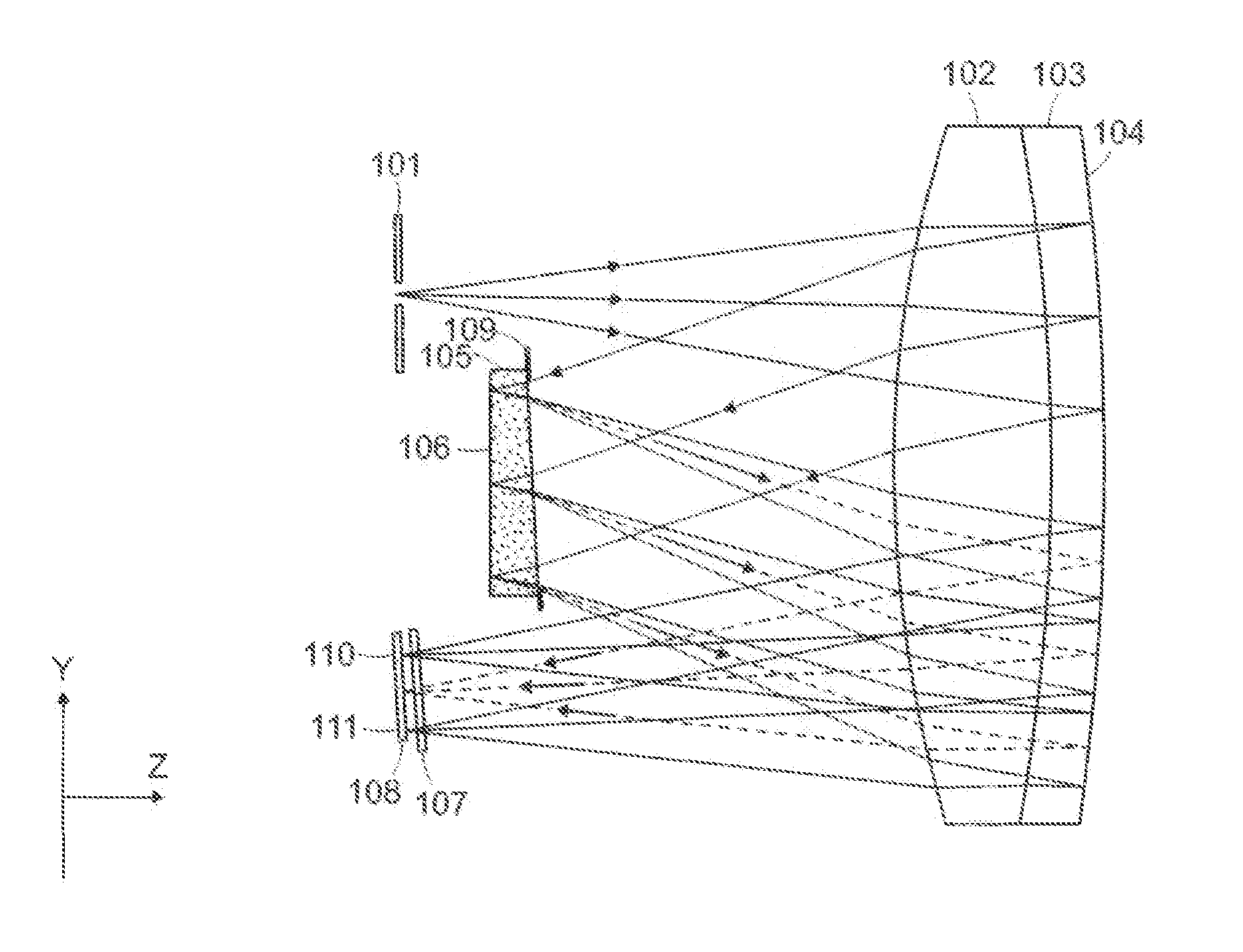
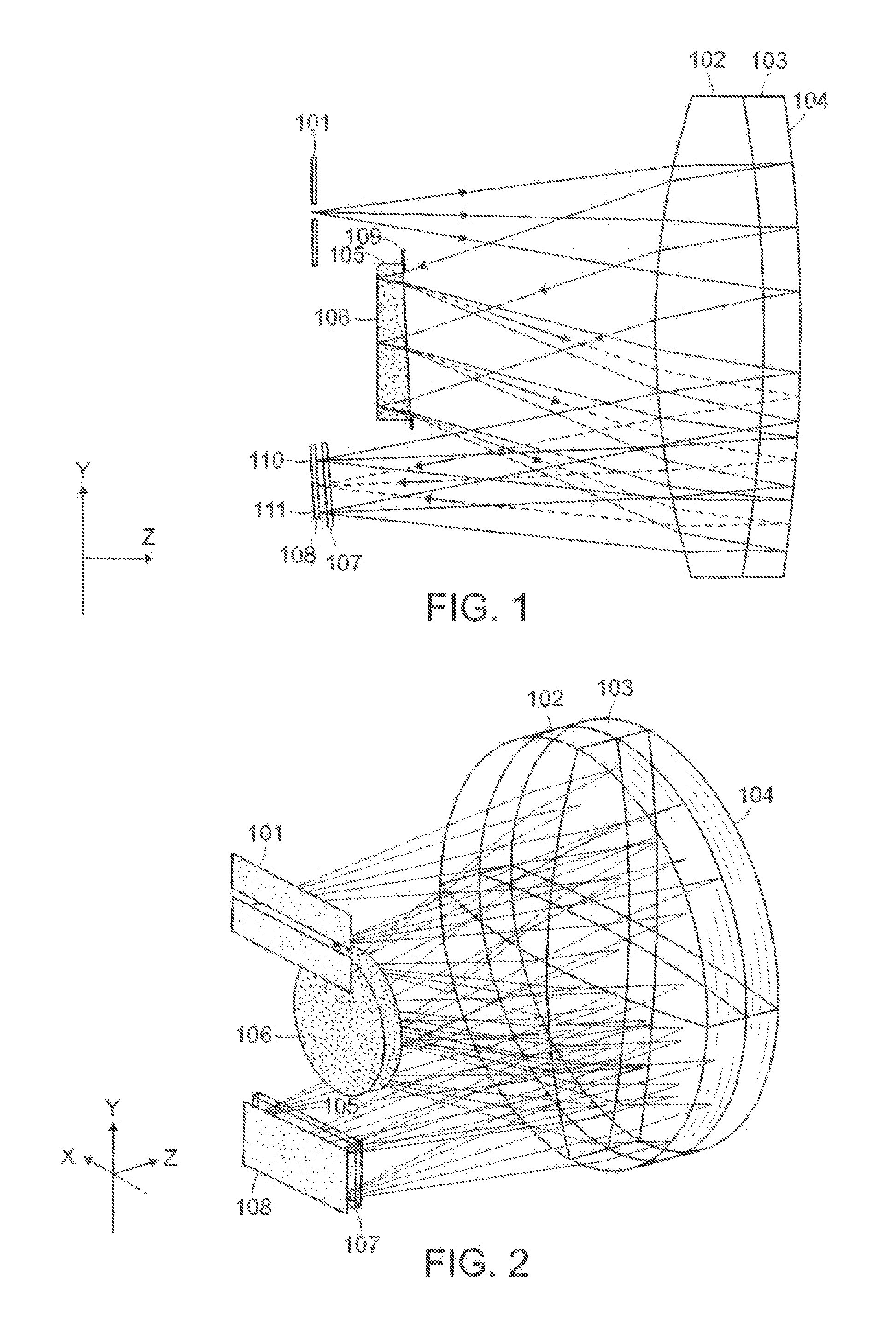
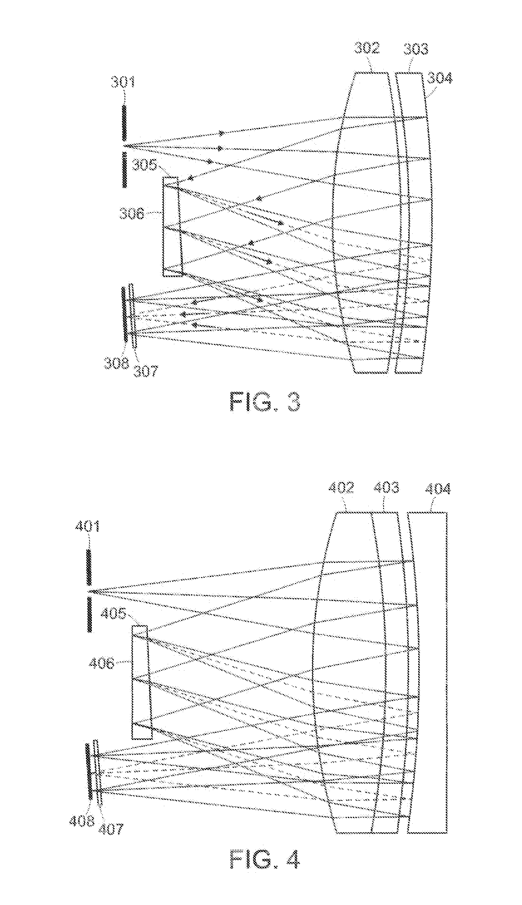
[0028]This visible-infrared plane grating imaging spectrometer was developed for remote sensing for smaller scale unmanned aerial vehicles. With fewer optical elements to assemble, and an easily fabricated plane grating, it is easier to fabricate and assemble than the reflective optical systems utilizing convex gratings. Use of conventional replicated gratings leads to lower stray light than the diamond turned visible gratings with their high surface roughness grooves. The spatial keystone and spectral smile have been controlled over the full wavelength range, to ensure the purity of the spectral data received from the ground footprints which facilitates the accuracy of the spectral matching algorithms.

[0029]Referring now to FIG. 1 and FIG. 2, one particular embodiment is shown of a visible-infrared plane grating imaging spectrometer constructed in accordance with the present invention with the visible through infrared being dispersed and focused onto the detector. The grating rulin...


PUM


Abstract

An imaging spectrometer, covering the visible through infrared wavelengths, which disperses the light by a plane diffraction grating behind a wedged optical element. This design uses an achromatic doublet lens with a reflective coating on its convex back surface to produce the spectra on a flat detector. Spatial keystone distortion and spectral smile are controlled to less than one tenth of a pixel over the full wavelength range, facilitating the use of simple retrieval algorithms.

Description

[0001]This application claims priority to provisional application Ser. No. 61 / 847238 filed Jul. 17, 2013, the contents of which are incorporated herein by reference.[0002]This invention was made with government support under Contract Na. FA8721-05-C-0002 awarded by the U.S. Air Force. The government has certain rights in the invention.BACKGROUND OF THE INVENTION[0003]1. Field of Endeavor[0004]The present invention relates to an imaging spectrometer, and more to an arrangement of optical elements to provide full spectral imaging over a wide waveband, in this case covering the visible through infrared in a compact instrument.[0005]2. State of Technology[0006]The challenge in imaging spectrometers is to make them small enough to fit in the small unmanned aerial vehicles which are now available. For remote sensing purposes, these aerial vehicles present a savings in operating costs. Small. imaging spectrometers are also advantageous for man-portable instruments and for fitting into exis...

Claims


Application Information

Patent Timeline
IPC IPC(8): G01J3/18G01J3/02G01J3/28
CPCG01J3/2823G01J3/0256G01J2003/1273G01J2003/2826G01J2003/1204G01J3/1804G01J3/0205G01J3/0208G01J3/021
Inventor CHRISP, MICHAEL, P.
Owner MASSACHUSETTS INST OF TECH
Learn More