High temperature insulated pipelines

a technology of pipelines and insulated conduits, applied in the direction of corrosion prevention, coatings, auxilary devices for sludge, etc., can solve the problems of reduced or lost production, reduced or omitted conduits, and the need to replace pipeline sections or entire systems with corresponding loss of asset valu

Inactive Publication Date: 2015-02-12
SHAWCOR LTD
View PDF5 Cites 12 Cited by
  • Summary
  • Abstract
  • Description
  • Claims
  • Application Information

AI Technical Summary

Benefits of technology

[0014]In one aspect, there is provided an insulated high-temperature transport conduit for use in undersea environments. In an embodiment, the conduit comprising: (a) a continuous steel pipe made up of one or more pipe sections, wherein the steel pipe has an outer surface and an inner surface; and (b) a first layer of thermal insulation provided over the outer surface of the steel pipe, wherein the first layer of thermal insulation is comprised of a p

Problems solved by technology

Both of these phenomena are related to the temperature of the fluid, and in extreme cases the conduit can become severely constricted or even blocked.
This in turn can lead to reduced or lost production.
In particularly serious cases this may lead to the need to replace sections of pipeline or entire systems with corresponding loss of asset value.
Hence, the traditional thermal insulation foam technology used in shallow waters and the associated design and test methodologies may not be applicable to deep-water projects, where the depths may exceed about 1,000 meters.
In cases of long pipe tiebacks, for example subsea-to-beach tiebacks, and in cases where the service temperature is above approximately 150° C., there exist limitations with current technology that may hinder the successful development of offshore, deep water oil or gas fields.
Limitations and deficiencies of these technologies in

Method used


Image

  • High temperature insulated pipelines
  • High temperature insulated pipelines
  • High temperature insulated pipelines

Examples


first embodiment

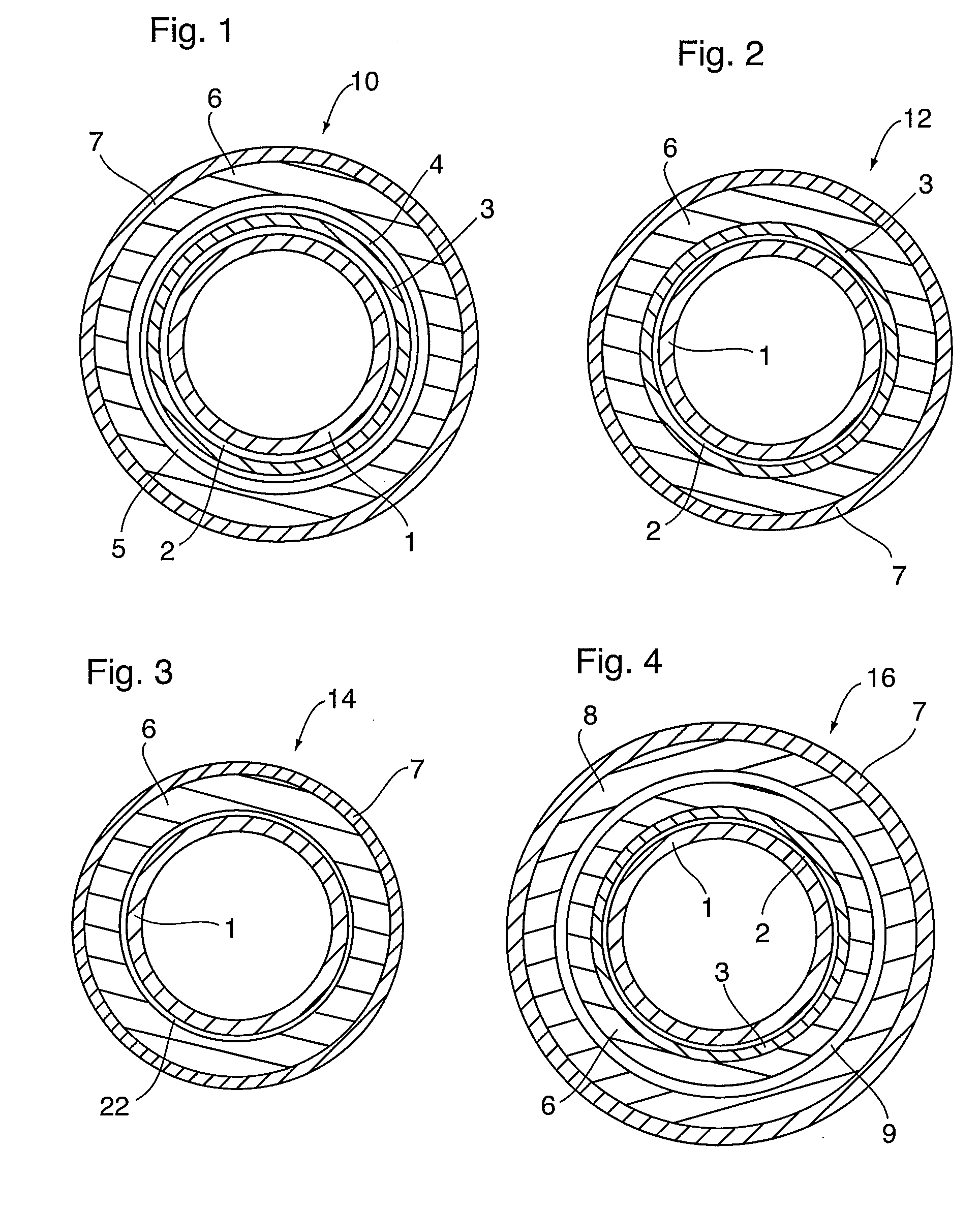
[0066]FIG. 1 illustrates a transverse cross-section of an insulated oil and gas pipeline 10 according to a The insulated pipeline 10 includes one or more sections of steel pipe 1 in which the insulating and protective coating includes a three-layer corrosion protection system. According to this system, the steel pipe 1 is coated with a corrosion protection layer 2 comprised of a high temperature corrosion protection material as described below, an intermediate first adhesive layer 3 applied over the corrosion protection layer 2, and a first protective topcoat 4 applied over the first adhesive layer 3. The first protective topcoat 4 provides added corrosion and mechanical protection and the adhesive layer 3 provides an adhesive bond between the topcoat 4 and the underlying corrosion protection layer 2. The topcoat 4 is shown in FIG. 1 as a relatively thin layer between the adhesive layer 3 and the overlying insulation layers described below. The composition and thickness of the topc...

third embodiment

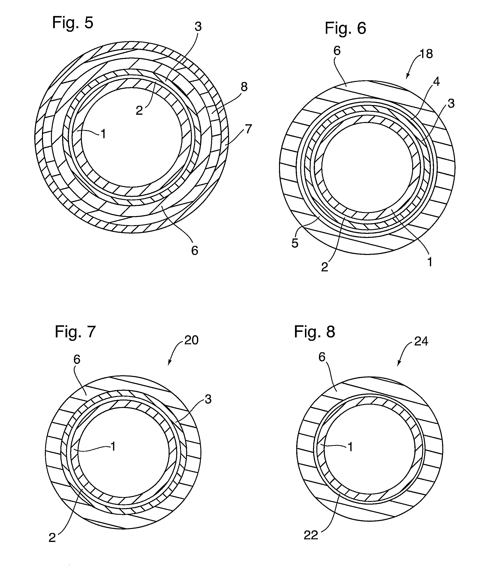
[0068]As an alternative to the multi-layer corrosion protection systems illustrated in FIGS. 1, 2 and 4, the steel pipe 1 may instead be provided with a single-layer composite corrosion protection layer wherein the high temperature corrosion protection material described below, adhesive and polymer topcoat components are pre-mixed and applied onto the pipe 1 as a variably graded coating. FIG. 3 illustrates a transverse cross-section of an insulated oil and gas pipeline 14 according to the invention. The insulated pipeline 14 includes one or more sections of steel pipe 1 provided with such a single-layer composite corrosion protection coating 22.

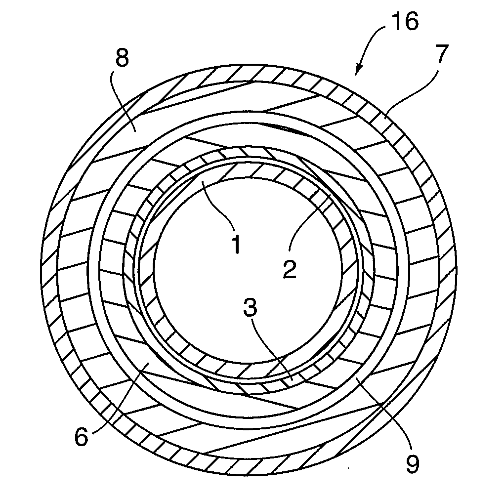
[0069]In the insulated oil and gas pipelines according to the embodiments disclosed herein also comprise one or more thermal insulation layers. The pipelines 10, 12 and 14 illustrated in FIGS. 1 to 3 include only a first thermal insulation layer 6, whereas the pipeline 16 of FIG. 4 is provided with a first (inner) insulation layer 6 and a sec...


PUM

PropertyMeasurementUnit
Temperatureaaaaaaaaaa

Abstract

An insulated high-temperature transport conduit for use in undersea environments. The conduit comprises a continuous steel pipe having at least a first layer of thermal insulation provided over its outer surface. The first layer of thermal insulation comprises a polymer composition having a thermal conductivity of less than about 0.40 W/mK and long-term heat resistance at continuous operating temperatures within the range from about 150° C. to above about 205° C. The first thermal insulation layer comprises a polymer composition comprising a polymer selected from the group consisting of one or more fluoropolymers, hydrogenated nitrile butadiene rubber (HNBR), and a blend of one or more fluoropolymers with HNBR. The conduit may further comprise second and third layers of insulation on top of the first layer, along with a corrosion protection coating underlying the first thermal insulation layer.

Description

CROSS-REFERENCE TO RELATED APPLICATIONS[0001]This application claims priority to and the benefit of U.S. Provisional Patent Application No. 61 / 863,976 filed Aug. 9, 2013; and U.S. Provisional Patent Application No. 62 / 021,751 filed Jul. 8, 2014.FIELD OF THE INVENTION[0002]The present invention relates to insulated fluid and / or gas transport conduits, and methods for the production and application thereof. More particularly, the insulated transport conduits comprise undersea pipelines for carrying single or multi-phase fluids such as oil, gas and water, particularly such pipelines operating at temperatures from about 150° C. to above about 205° C.BACKGROUND OF THE INVENTION[0003]There is increasing demand in the oil and gas industry for higher performance thermal coatings to insulate and protect off-shore transport conduits operating at temperatures from about 150° C. to above about 205° C. In order to maintain the conduit at the required operating temperatures in an undersea environ...

Claims


Application Information

Patent Timeline
IPC IPC(8): F16L59/02F16L59/14
CPCF16L59/143F16L59/029F16L58/181F16L59/20F16L13/0272B29C39/10B29C33/0011B23K31/02B23K37/00F16L58/1081F16L1/161F16L59/14B23K31/027F16L9/02F16L9/22F16L58/1054
Inventor WAN, EILEENJACKSON, ADAMSIMONSEN, EIRIK
Owner SHAWCOR LTD
Why Eureka
Try Eureka