Multi-stage plasma reactor system with hollow cathodes for cracking carbonaceous material

a plasma reactor and hollow cathode technology, applied in the field of energy-efficient equipment and processes for cracking carbonaceous materials, can solve the problems extremely rapid tendency of plasma gas atoms or ions to increase to extremely high temperatures in a very short time, and give off enormous amounts of hea

Active Publication Date: 2015-02-12
CHNA ENERGY INVESTMENT CORP LTD
View PDF3 Cites 8 Cited by
  • Summary
  • Abstract
  • Description
  • Claims
  • Application Information

AI Technical Summary

Benefits of technology

[0070]The above novel structure design of the plasma reactor system according to the present invention has following advantages and characteristics:

Problems solved by technology

Generally, where an electric arc is applied as a heat source, the electric arc passes through the gas, for example hydrogen gas, causing temperature of the gas to increase to extremely high temperatures in a very short time.
Once plasma high temperature gas, such as plasma hydrogen, leaves the electric arc, there is an extremely rapid tendency for the plasma gas atoms or ions, for example hydrogen atoms to recombine into molecules, and if doing so, they give off tremendous amounts of heat.
In this way, all electricity input from the thin arc zone, i.e. a large amount of energy enough to raise the powder temperature to above 1800 K, led to unreasonable over-aggregation of energy and inevitable exposure of over-concentrated heat to the reactor wall thereby causing overheating of the wall.
The heat essentially removed from the neighbor of the wall for protection of the wall accounts for about half of the total electricity input, as a result, a lot of valuable energy had to waste out.
Furthermore, the extreme high temperature occurrence on the specific region greatly challenged the design of the reactor wall structure, selection of the wall material, as well as made the wall protection in big troubles.
However, due to the high-speed moving downward of the plasma jet and thereby forming strong obstacle to fluid-powder mixing, so that the contact and thermal transfer efficiency between the coal powder and plasma stream is weakened with negative effect on the reactor performances while such reactor structure and arrangement of feeding caused the caking phenomenon hardly be avoided due to the coal powder or gaseous and liquid hydrocarbons continuously flushing and striking on the wall surface.
However, the reactor disclosed in this patent document has still not overcome all of the above identified shortcomings.
For example, the structure of the present reactor could not allowed to make freely such adjustment as it needs to increase or optimize the reaction temperature and / or time of the carbonaceous material powder and freely lengthen the height of the prior single-stage reactor according to the reaction temperature as requested by the maximum yield of cracked products, for example acetylene.
The rapid drop of hot stream temperature along the present reactor longitudinal direction results in that the reacting jet flow must be quenched to maximize the cracked products yield in a relatively short moving distance and hence the carbonaceous material to cracked products conversion is greatly limited.
Meantime as previously stated, serious energy waste and over-high temperature distribution in neighbor of reactor inner wall also are big technical problems not to allow being ignored. in the plasma reactors and cracking methods disclosed in the above all prior documents references, the region where carbonaceous material contacts and mixes with plasma stream always kept away from the highest temperature region caused by electric arc, this fact would result in the consequence that thermal transfer efficiency is greatly reduced, and hence operational temperature of carbonaceous material pyrolysis, i.e. devolatilization and the temperature of following gas phase reaction of volatiles were greatly decreased, thereby the yield of cracked products is apparently lowered, as well as energy efficiency of the reactor correspondingly dropped while it is also possible that overheating on reactor wall or neighbor thereof and energy waste were caused.

Method used


Image

  • Multi-stage plasma reactor system with hollow cathodes for cracking carbonaceous material
  • Multi-stage plasma reactor system with hollow cathodes for cracking carbonaceous material
  • Multi-stage plasma reactor system with hollow cathodes for cracking carbonaceous material

Examples


example 2

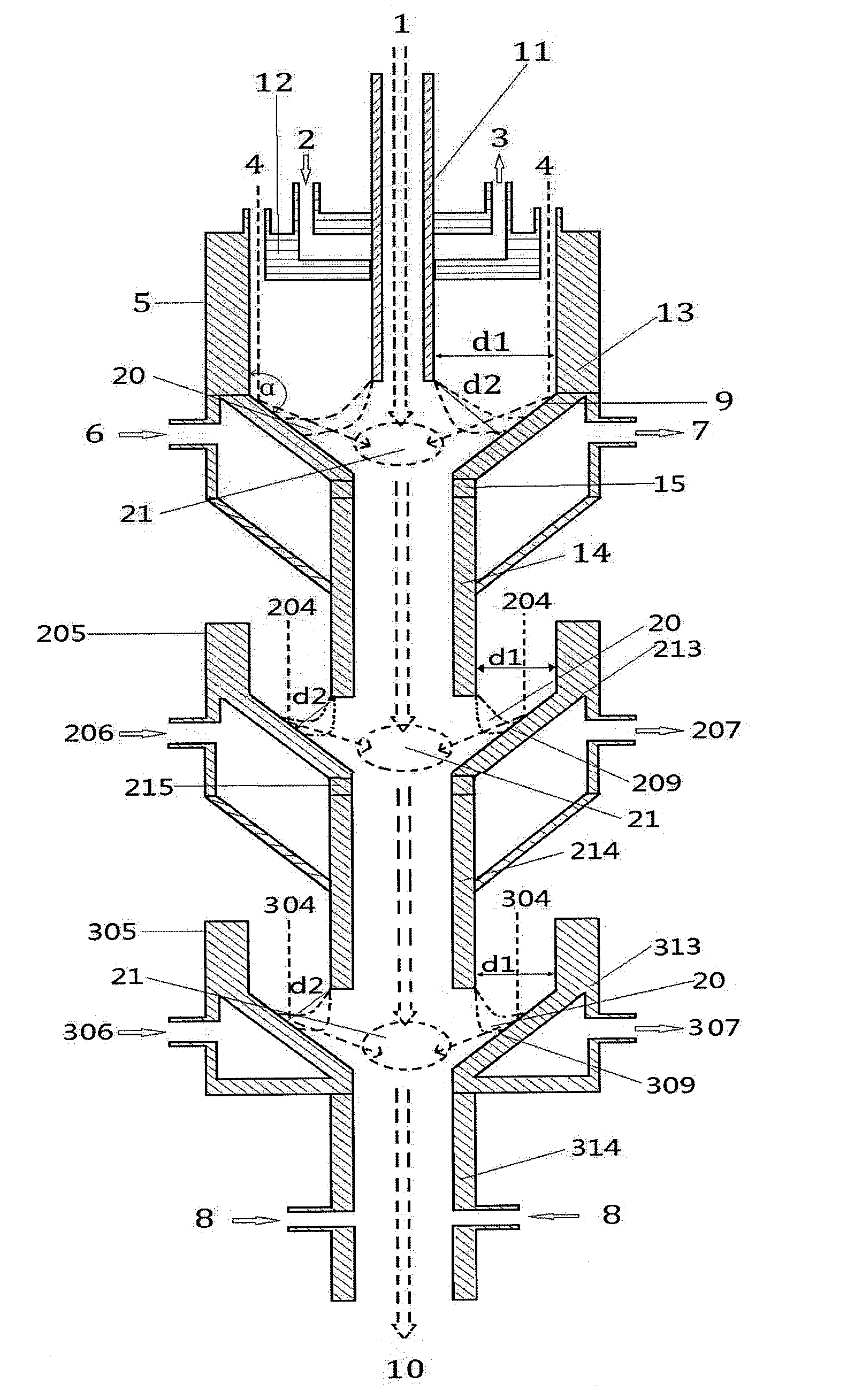
[0088]The experiment described in the example 1 was repeated except that the plasma reactor system as shown in FIG. 4 was substituted by the plasma reactor system as shown in FIG. 4, in which the power input of first hollow cathode and / or first anode in the present plasma reactor system was 10 kW while the power inputs of second and third hollow cathodes and / or anodes in the present plasma reactor system were 15 kW so as to form the electric arc generating plasma stream. As shown in FIG. 5, the reactor system mainly consisted of the hollow cathodes 11, 14 and 214, anodes 5, 205 and 305, inlets of the working gases 4, 204 and 304, first reaction tube 14 used as second hollow cathode, second reaction tube 214 used as third hollow cathode and third reaction tube 314, inlets of quench medium 8 and inlet of quenched products 10, in which the closest horizontal distances between the outer surfaces of the hollow cathodes 11, 14 and 214 and the interior surfaces of the anodes 5, 205 and 305...


PUM


Abstract

Disclosed is a multi-stage plasma reactor system with hollow cathodes for cracking carbonaceous material with each stage comprising: hollow cathodes and hollow anodes cooled by recycling cooling medium or refrigerant; working gas inlet(s); inlet(s) of carbonaceous material and carrier gas as feedstock; reaction tubes in connection with the anode or cathode, in addition, the reactor system also comprises: at least one inlet(s) of quench medium located lower portion of last one of the reaction tubes; and at least one outlet(s) of quenched products and gases located on bottom or lower portion of last one of the reaction tubes, wherein chambers are formed between the first hollow cathode or the hollow cathode used as the reaction tube of any stage and the anode so as to generate plasma gas and / or electric arc therein, generated plasma gas jet fully contacts and efficiently mixes with the carbonaceous material and carrier gas as feedstock and / or volatiles caused by pyrolysis within or nearby highest temperature region of the chambers, and pyrolysis of the carbonaceous material and / or gas-phase reaction of volatiles are occurred. The present reactor system has excellent energy efficiency and higher cracked products yield.

Description

FIELD OF INVENTION[0001]The invention relates to an energy efficient equipment and process for cracking carbonaceous material with volatiles content to produce a high yield of cracked products, especially to a multi-stage plasma reactor system with hollow cathode for cracking carbonaceous material as well as a process for cracking carbonaceous material by using the multi-stage plasma reactor system, more particularly, also to a process for producing acetylene by using the multi-stage plasma reactor system.PRIOR ART[0002]Conventionally, carbonaceous materials, together with other components such as hydrogen, are heated by an electric arc device or other suitable sources of heat which are well known to those skilled in the art so as to be cracked or pyrolyzed. The composition that is produced as a result of the decomposition of the carbonaceous matter will depend on the reaction conditions existing in the decomposition or reaction zone. It is well-known that the formation of certain c...

Claims


Application Information

Patent Timeline
Patent Type & Authority Applications(United States)
IPC IPC(8): B01J19/08B01J19/24
CPCB01J19/088B01J19/2415B01J2219/0894B01J2219/0869B01J2219/0871B01J2219/0809C10J2200/12C10J3/485C10J3/721C10J3/78C10J3/84C10J2300/093C10J2300/0946C10J2300/0959C10J2300/0976C10J2300/1238C10J2300/1807B01J2219/0815B01J2219/0824B01J2219/0875B01J19/243C10J3/00
Inventor LI, XUANYAN, BINHANGWU, CHANGNINGCHENG, YIGUO, YI
Owner CHNA ENERGY INVESTMENT CORP LTD
Why Eureka
Try Eureka