Method of making a 3D object from composite material

a composite material and object technology, applied in the field of 3d objects made of composite materials, can solve the problems of adding to costs and not entirely satisfying the production of a new mould, and achieve the effect of light weigh

Inactive Publication Date: 2015-03-05
TRONDL WILLIAM ANTON
View PDF4 Cites 15 Cited by
  • Summary
  • Abstract
  • Description
  • Claims
  • Application Information

AI Technical Summary

Benefits of technology

[0009]In a first aspect the invention provides a method of producing an object made of a composite material said object being relatively strong and light weight and having a complex three-dimensional configuration, said method comprising the steps of a) providing a plurality of appropriately shaped sections bonded together into the three-dimensional configuration, each section comprising a suitable core material with a suitable laminated face extending to an edge thereof, said configuration having first and second surfaces incorporating said edges; b) laminating or otherwise sealing said surfaces and edges; c) wherein said laminated faces form a series of structural webs connecting said first and second surfaces; and d) wherein said sections provide rigidity to the nascent configuration when said sections are sequentially assembled.
[0010]The invention is partly predicated on the inventor's surprising realization that a complex 3 dimensional object may be made using I-beam-like webs of structural material where the first and second surfaces (which correspond to the capped flanges of an I-beam) form a continuous outer surface of the object. Specifically the method involves bonding a series of shaped sections of material each with a laminated face to form the desired object which when laminated, ties the internal and external laminations together to form an array of structural members. The method provides the added advantage that the object may be formed without using a mould. This means that changes to the design of an object do not involve the expensive step of having to produce a new mould.
[0024]The webs are formed by sealing the external surfaces and edges of laminated faces. These webs tie the surfaces together creating an array of I-beam like structures throughout the object, the lamination forming a unitary or integral array of the functional equivalent of a capped flange in an I-beam. Specifically, the lamination is bonded to core material and the edge of webs in a way that provides maximum adhesion and hence provides tensile and torsional strength to the object.
[0036]Optionally the sections are of such a shape that when joined the laminated faces or layer of structural material are parallel or substantially parallel thus providing evenly spaced webs or ties throughout the material. Alternatively the sections may be cut from sheet material that has variable tapered thickness in one axis providing sections which are wedged shaped resulting in the laminated faces or layers of structural material being non-parallel. This being advantageous when constructing a spherical, conical or cylindrical exterior profile where webs are to be positioned radially, hence providing an increase in longitudinal strength. It may also be beneficial to have variably spaced webs and so allow more strength in highly stressed areas of the object. This may be achieved by sections cut from sheets of different thicknesses.

Problems solved by technology

While the above proposals may address some of the issues with production of light weight material having a high strength to weight ratio they are not entirely satisfactory because of difficulty of use and / or high production costs, particularly in relation to the production of complex 3D objects.
Further changes to the design of an object may involve the production of a new mould adding to costs.

Method used


Image

  • Method of making a 3D object from composite material
  • Method of making a 3D object from composite material
  • Method of making a 3D object from composite material

Examples


example 1

Production of a Complex 3D Object

[0060]A complex 3D object may be produced by the following steps:

[0061]Step 1.

[0062]An object is designed creating a plan in 3 dimensions which plan is divided into multiple sections by strategically spaced planes so as to provide a series of sectional profiles of the 3 dimensional form. The 3 dimensional form is conveniently designed with CAD or CAM computer software. Utilizing the facilities available in the software application, an array of planes can easily be generated and the profiles exported to individual files and / or defined as individual objects. These objects or files could be 2 dimensional or 3 dimensional depending on the type of machine cutting process to be employed in step 3.

[0063]During the CAD / CAM design process allowance may be provided to ensure proper alignment of each section which is carried out in step 4. This is achieved by allocating matching drill points for each adjacent profile section. During step 3, the cutting process,...

example 2

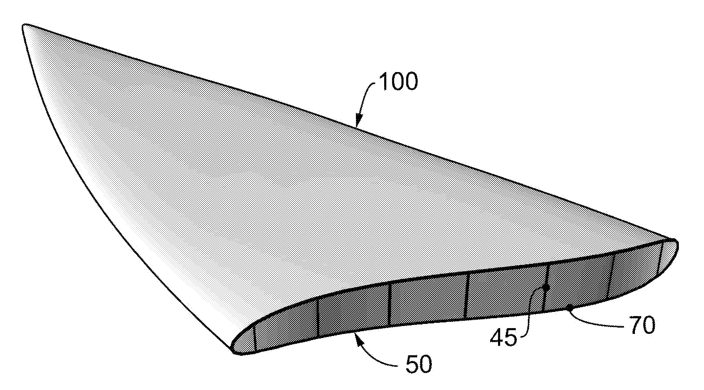
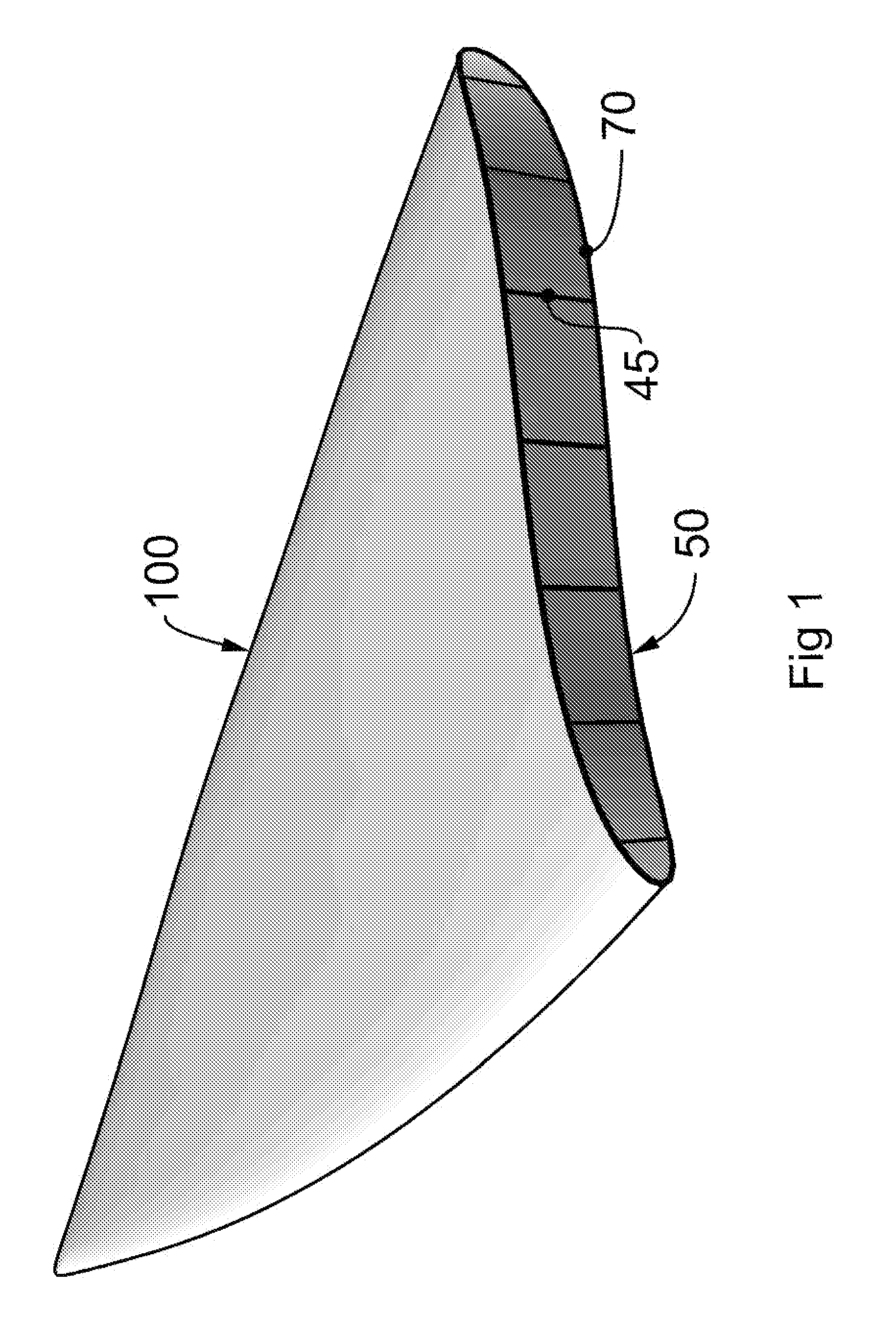
Production of Trimaran Hull

[0080]Boat hull external and internal surfaces for a 14 foot trimaran were designed by CAD utilizing Rhinoceros (Rhino). This is a stand-alone, NURBS-based 3-D modeling software, developed by Robert McNeel & Associates. These external and internal surfaces were notionally sliced into 26 mm thick “sections” and parts for CNC machining were developed from these sections along with drill points for locating pegs for each part ensuring properly positioned assembly of parts. Each part was exported to its own separate DXF file. There were 922 parts for this 14′ hull.

[0081]Polyurethane core material by the trade name Divinycell® (DIAB) was used for the core or substrate material of the trimaran hull. Divinycell® is relatively expensive but rated for marine applications. The most common size sheeting is 8×4′ and 1″ thickness and 60 kg / m3 density was used for this project.

[0082]Fiber glass was used as the structural material for forming the laminated faces and surf...

example 3

Testing of Material

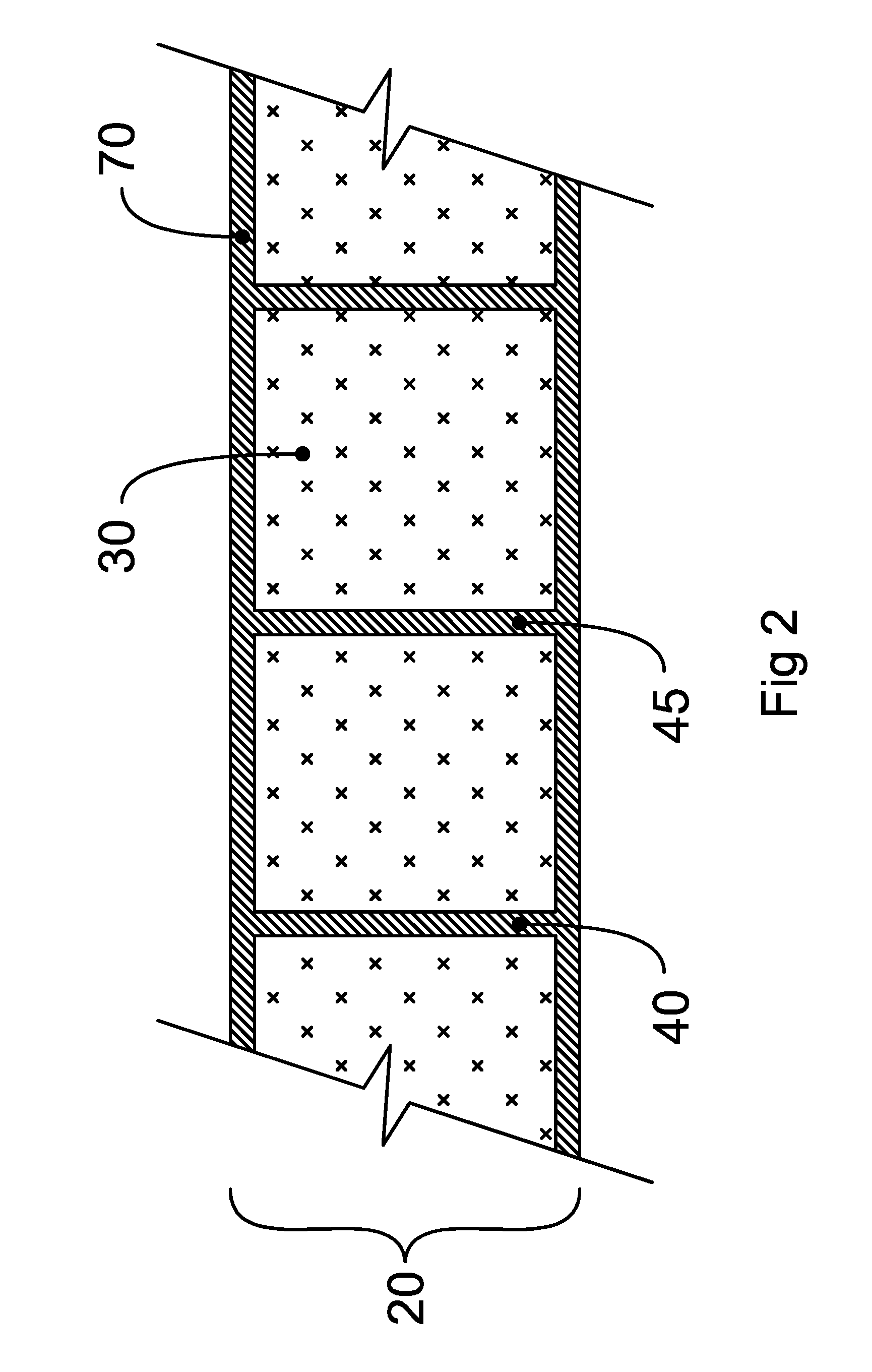
[0099]Test beam samples were manufactured consistent with the method of the invention. The test beams consisted of 100 mm wide beams with webs and surfaces of 3ply 8 oz epoxy fibreglass and 60 kg / m3 polyurethane foam. Beam thickness was 28 mm and webs where spaced almost symmetrically at 26 mm longitudinally, 4 webs per beam. Other test beam samples were manufactured without webs in a standard sandwich composite configuration. These beams were also 100 mm wide and also used 3ply 8 oz epoxy fibreglass on upper and lower surfaces. 3 different thickness beams were manufactured, with 60 kg / m3 density foam core of 1.0″, 1.5″ and 2.0″ resulting in beam thicknesses of 27.5 mm, 40.5 mm and 53 mm respectively. Testing was carried out using a single point load by way of steel bar radius 30 mm contacting beam surface perpendicular to beam length. The 3 standard beams and the webbed beam were each tested while centred on supports 300 mm apart and the point load applied to bea...


PUM

PropertyMeasurementUnit
thickaaaaaaaaaa
densityaaaaaaaaaa
weightaaaaaaaaaa

Abstract

The invention provides a method of producing an object made of a composite material said object being relatively strong and light weight and having a complex three-dimensional configuration. The method involves bonding a series of shaped sections of material each with a laminated face to form the object which when laminated, ties the internal and external laminations together to form an array of structural members. The method provides the added advantage that the object may be formed without using a mould.

Description

TECHNICAL FIELD[0001]The present invention relates to production of 3D objects made of composite material which are relatively strong and light weight.BACKGROUND ART[0002]The need for strong light weight material for construction of all types of objects such as vehicles including watercraft and aircraft has been ongoing. Fiberglass was an innovation to the boat building and craft industries in the 1950s.[0003]Building on 1950s technology a number of proposals to provide strong light weight material have been put forward. These include the use of composite materials in male / female molds such as in U.S. Pat. No. 5,526,767 by McGuiness, its use in closed molds as in U.S. Pat. No. 4,910,067 by O'Neill and improved hybrid fiberglass composites which resist impact damage such as those disclosed in U.S. Pat. No. 7,740,392 by Kismarton.[0004]GB 1307868 in the name of CMN dates from 1970 and discloses use of lathes made of foam in the construction of a boat hull. Each lath is of a constant t...

Claims


Application Information

Patent Timeline
Patent Type & Authority Applications(United States)
IPC IPC(8): B32B1/00B32B37/18
CPCB32B1/00B32B37/18B32B2605/12B32B2605/18B32B2250/44B29C70/086B29C70/865B29D99/0021B29L2031/307B29L2031/5272B32B3/00B32B3/18B32B5/245B63B1/125B63B2005/242B63B32/40B63B32/50B63B32/57Y02T50/40Y10T156/10B29C65/00B32B3/26B63B5/24B63B27/14B64C1/00
Inventor TRONDL, WILLIAM ANTON
Owner TRONDL WILLIAM ANTON
Why Eureka
Try Eureka