Carbon nanocomposite sorbent and methods of using the same for separation of one or more materials from a gas stream

a technology of carbon nanocomposite and sorbent, which is applied in the direction of physical/chemical process catalysts, separation processes, and other chemical processes, can solve the problems of increasing the amount of standard sorbents (e.g., activated carbon) needed to serve the market, increasing the cost of standard sorbents, and reducing the stability of recycling and processing, so as to promote oxidation of pollutants, hinder the sorption of pollutants, and enhance the sorption of pollutan

Active Publication Date: 2015-04-09
MIDWEST ENERGY EMISSIONS CORP
View PDF4 Cites 23 Cited by
  • Summary
  • Abstract
  • Description
  • Claims
  • Application Information

AI Technical Summary

Benefits of technology

[0011]Surprisingly, despite activated carbons being routinely used to capture pollutants in flue gas streams, carbon nanocomposites have not been used before for gas-phase mercury capture. Traditional thinking is that an excess of inorganic support such as clay in the carbon nanocomposite hinders the sorption of the pollutant on the carbon. However, surprisingly, in accord with some embodiments of the present invention, the non-carbon parts can enhance the sorption of pollutant on the proximate carbon graphene layer. The basal planes of the carbon portions of the nanocomposites are indeed largely hindered within carbon nanocomposite structures. However, the carbon edge structures are very well exposed in the structures, and these are the part of the carbon that is active for pollutant capture (e.g., mercury, selenium, arsenic, and the like). As described herein, the graphene edge structures can be promoted by reaction with a halogen, hydrogen halide, or ammonium halide to produce a carbocation edge structure that is highly reactive for oxidation and capture of pollutants such as mercury.
[0012]Since support materials such as clays are by themselves inert, the promotion of oxidation of pollutants by the carbon layer caused by certain support materials is also unexpected. However, in accord with some embodiments of the present invention, a polyanionic aluminosilicate layer (e.g., from clay) can stabilize the development of cationic sites on the proximate graphene carbon structures that are essential for oxidation of pollutants such as mercury. The same stabilizing effect can occur with a carbon-diatom (silicate) nanocomposite or other nanocomposites composed of graphene layers and polar inorganic structures.
[0013]In embodiments that include a nanocomposite that is promoted via hydrogen halide compound obtained from degradation or reaction of the corresponding ammonium halide, another advantageous role for the inorganic portion can be in providing a binding site for the ammonia that is released from either the decomposition or reaction of the ammonium salt. The bound ammonia forms a complex with basic character that reacts with SO2 in the flue gas and prevents their interference with the capture on the edge structure of pollutants such as mercury.
[0014]In another advantage of inorganic support in embodiments that include clay as the support, the clay is stabilized to dispersion in an aqueous medium. Clays are usually difficult to filter or separate from an aqueous medium, but in the form of a nanocomposite with carbon, the material can be easily separated from an aqueous medium by filtration. Thus, the nanocomposite can be conveniently utilized to capture mercury in an aqueous environment.
[0015]The present invention advantageously can separate a material (e.g., a pollutant) from a gas that includes that material more efficiently than other methods. The present invention provides certain advantages over other methods and materials for the removal of mercury from mercury-containing gas. The method and materials of various embodiments of the present invention can capture and remove mercury from a gas more efficiently than other methods of mercury removal. The method and materials of various embodiments of the present invention can operate more efficiently than other methods of mercury removal. For example, the method and materials of various embodiments can remove a given amount of mercury for a smaller amount of financial expenditure, as compared to other methods. For example, the method and materials of various embodiments can remove a larger amount of mercury for a given mass of carbon, as compared to other methods of removing mercury, including as compared to other methods of removing mercury that include a carbon sorbent. Thus, the method and materials of various embodiments can result in the use of less sorbent material (e.g., less carbon overall), as well as the disposal of less used sorbent material, than other methods of mercury removal.

Problems solved by technology

Mercury (Hg) emissions have become a health and environmental concern because of their toxicity and ability to bioaccumulate.
The amount of standard sorbents (e.g., activated carbon) needed to serve the market is large.
Standard sorbents are not always effective and become more expensive as injection rates increase.
None of these is a carbon nanocomposite; rather, they are typically a polymer film deposited on a support and suffer limitations from stability and difficulty of recycling and processing.
This technology suffers from the difficulty of having to effectively irradiate combustion effluent containing fine particulate.
It is suspected that the Ag nanocomposite represents a significant environment risk in itself, as well as being a high-cost sorbent.
These non-carbon sorbents have higher cost and slower kinetics than desirable.

Method used


Image

  • Carbon nanocomposite sorbent and methods of using the same for separation of one or more materials from a gas stream
  • Carbon nanocomposite sorbent and methods of using the same for separation of one or more materials from a gas stream
  • Carbon nanocomposite sorbent and methods of using the same for separation of one or more materials from a gas stream

Examples


example process

[0091]In various embodiments, the carbon nanocomposite sorbent, method of mercury removal, and optional additives discussed herein have applicability to mercury control from the product or effluent gas or gases from gasification systems, syngas generators, and other mercury-containing gas streams, in addition to the flue gas from combustion systems. Thus, it should be understood that the terms combustion system and flue gas as used throughout this description can apply equally to gasification systems and syngas or fuel gas, as will be understood by those skilled in the art.

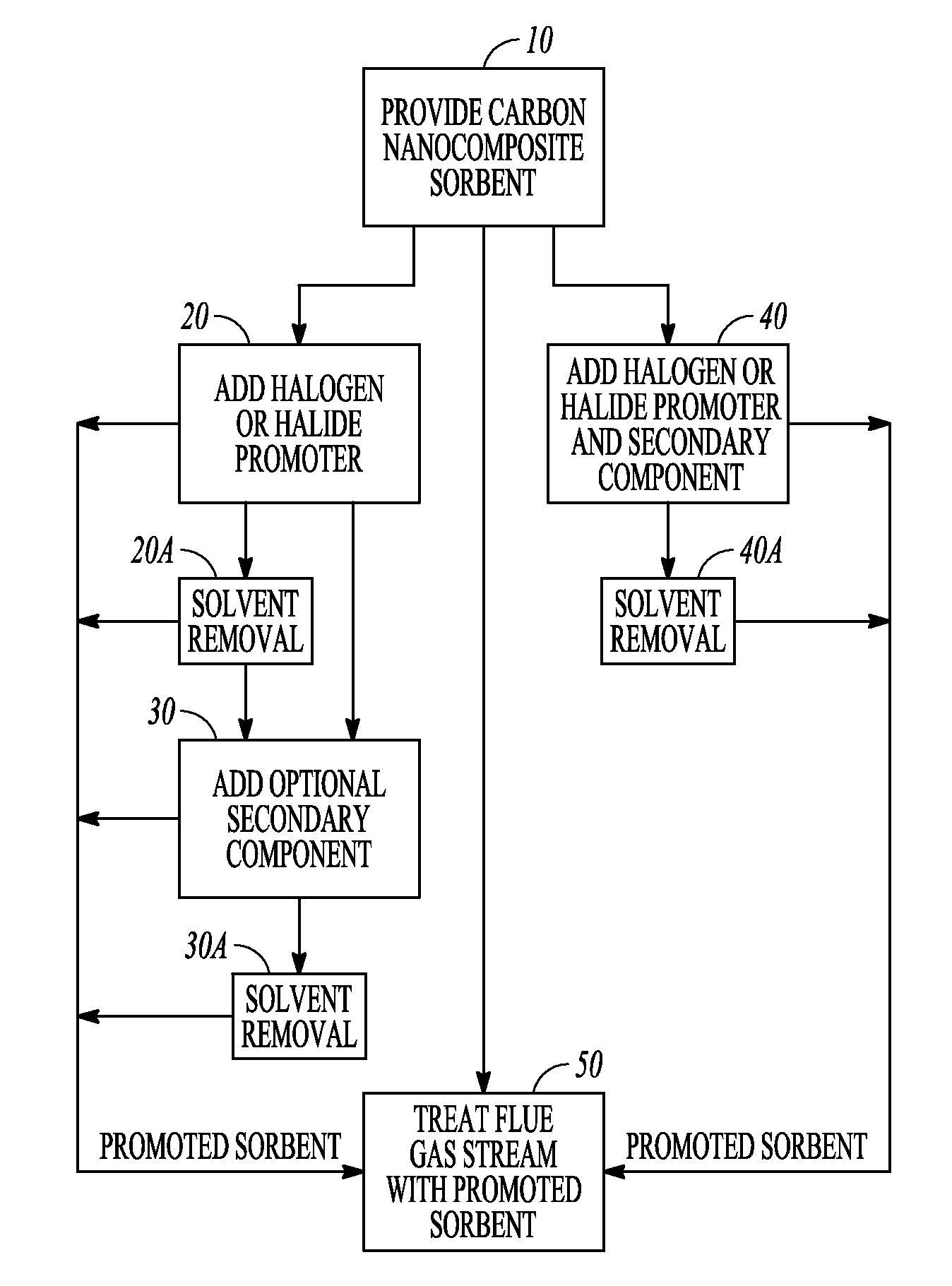
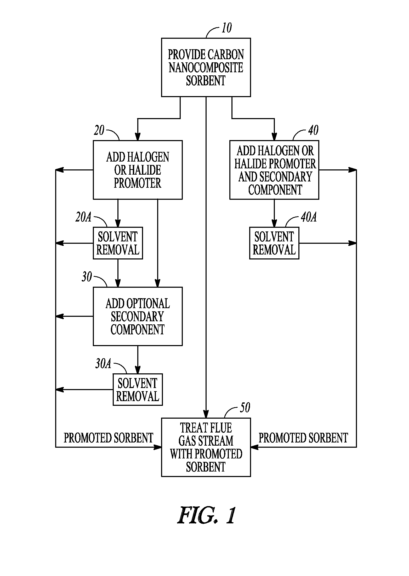
[0092]Referring now to FIG. 1, there is shown a block flow diagram illustrating methods for preparation of promoted carbon sorbents, in accordance with various embodiments. Block 10 illustrates providing carbon nanocomposite sorbent and adding a halogen or halide promoter that reacts with the carbon, illustrated at block 20, to produce a promoted carbon nanocomposite sorbent. In embodiments where a halogen or hali...

example 1

Mesoporous Activated Carbon (AC) Nanocomposites from Commercial Cane Molasses

example 1.1

NanoG-CM

[0116]High-surface-area montmorillonite (clay) obtained from Aldrich (200 g) was added rapidly to Brer Rabbit molasses (nonsulfurated) diluted with a smaller amount of water (200 g / 140 mL) and stirred to make a thick paste.

[0117]As soon as all the clay was wetted with the molasses, the paste was dried overnight at 110° C. to remove excess water. Alternatively, a smaller portion of the paste was heated for 1 min in a microwave. A smaller batch was dried more quickly (1 hour) in the oven at 110° C.

[0118]The dried solid was loaded in two batches in a cylindrical steel tube and heated to 700° C. in a tube furnace with a flow of nitrogen through the bed. The effluent gas was bubbled through a water trap. Heating was continued for 1 hour. The tube was cooled slowly to ambient under nitrogen and emptied. The resulting black chunks of composite carbon were weighed and ground in a mortar and pestle. The product nanocomposite was separated into two sieve sizes, greater than 325 mesh a...


PUM

PropertyMeasurementUnit
thicknessaaaaaaaaaa
thicknessaaaaaaaaaa
thicknessaaaaaaaaaa

Abstract

The present invention relates to carbon nanocomposite sorbents. The present invention provides carbon nanocomposite sorbents, methods for making the same, and methods for separation of a pollutant from a gas that includes that pollutant. Various embodiments provide a method for reducing the mercury content of a mercury-containing gas.

Description

CLAIM OF PRIORITY[0001]This application is a continuation application which claims the benefit of U.S. patent application Ser. No. 13 / 453,274, filed Apr. 23, 2012, which is incorporated herein by reference in its entirety.STATEMENT OF GOVERNMENT SUPPORT[0002]This invention was made with government support awarded by the U.S. Department of Energy (DOE) under DOE Cooperative Agreement Number DE-FC26-08NT43291 entitled “EERC-DOE Joint Program on Research and Development for Fossil Energy-Related Resources”; Subtask 4.8 entitled “Fate and Control of Mercury and Trace Elements”; EERC Fund Number 14990. The government has certain rights in this invention.BACKGROUND OF THE INVENTION[0003]Mercury (Hg) emissions have become a health and environmental concern because of their toxicity and ability to bioaccumulate. The U.S. Environmental Protection Agency (EPA) has issued regulations for the control of Hg emissions from waste-to-energy, cement production, and coal-fired power plants. Mercury i...

Claims


Application Information

Patent Timeline
Patent Type & Authority Applications(United States)
IPC IPC(8): B01J20/30B01J20/20
CPCB01J20/3078B01D2253/25B01J20/20B01D53/02B01D53/508B01D53/80B01J20/12B01J20/205B01J20/3204B01J20/324B01D2253/304B01D2253/108B01D2253/102B01D2253/11B01D2251/108B01D2258/0283B01D53/64B01D53/96B01D2257/602
Inventor OLSON, EDWIN S.PAVLISH, JOHN HENRY
Owner MIDWEST ENERGY EMISSIONS CORP
Why Eureka
Try Eureka