DLC Coating for an Optical IR Component and Optical IR Component Having Said DLC Coating

a technology of optical ir and dlc coating, which is applied in the direction of superimposed coating process, lighting and heating apparatus, instruments, etc., can solve the problems of high technological expenditure, high technological expenditure, and high cost of stacking many layers of this kind on top of one another, and achieves improved transmission of dielectric coating, high resistance of diamond coating, and advantageous spectral characteristics

Inactive Publication Date: 2015-04-23
JENOPTIK OPTICAL SYST
View PDF4 Cites 8 Cited by
  • Summary
  • Abstract
  • Description
  • Claims
  • Application Information

AI Technical Summary

Benefits of technology

[0015]The invention includes at least one layer of the DLC coating which is resistant to mechanical influences configured such that the outer surface is protected from exposure to mechanical influence, but unattenuated transmission to the at least one layer of antireflection coating located below the outer surface is prevented. This advantageous effect is achieved by the outer surface having a higher modulus of elasticity than the layers lying below it or than the areas of the at least one layer which lie below it. Therefore, the DLC coating is less elastic at its outer surface which is directly exposed to environmental conditions than at its inner surface.
[0023]It is extremely advantageous that the occurrence of abrupt transitions with sharply diverging elastic behavior of layers with respect to one another (expressed by moduli of elasticity) is prevented by means of an inventive configuration of the DLC coating. An occurrence of the disadvantageous eggshell effect is sharply reduced or completely prevented.
[0028]It has proven advantageous when the layer of the antireflection coating which directly contacts the inner surface of the DLC coating is made of germanium. A good bonding of the DLC coating to the antireflection coating is achieved by means of germanium. The layer can also be made of or can contain doped germanium.
[0033]It is very advantageous when a first determined wavelength range and a second determined wavelength range are provided, and the first determined wavelength range lies in the range of mid-wavelength IR radiation (3-8 μm) and the second determined wavelength range lies in the range of long-wavelength IR radiation (>8-15 μm).
[0034]As a result of the construction of an optical IR component with antireflection coating and a DLC coating according to the invention, the very high resistance of a diamond coating (DLC coating) is combined with an appreciably improved transmission of a dielectric coating or a coating with semiconductor materials.
[0035]The solution according to the invention makes it possible to achieve very advantageous spectral characteristics such as high transmission (e.g., at least 80%) and low reflection (e.g., at most 2%) in at least two separate determined wavelength ranges. The determined wavelength ranges can be entirely or partially wavelength ranges of mid-wavelength IR radiation and of long-wavelength IR radiation, for example.

Problems solved by technology

This would cause the optical IR component to be destroyed or would at least greatly impair its usability to an unforeseeable extent.
Stacking many layers of this kind on top of one another would entail a high technological expenditure.
While using fewer layers limits the technological expenditure, the freedom in the choice of materials is sharply curtailed because the gradient of decreasing moduli of elasticity must be brought about.

Method used


Image

  • DLC Coating for an Optical IR Component and Optical IR Component Having Said DLC Coating
  • DLC Coating for an Optical IR Component and Optical IR Component Having Said DLC Coating
  • DLC Coating for an Optical IR Component and Optical IR Component Having Said DLC Coating

Examples


Embodiment Construction

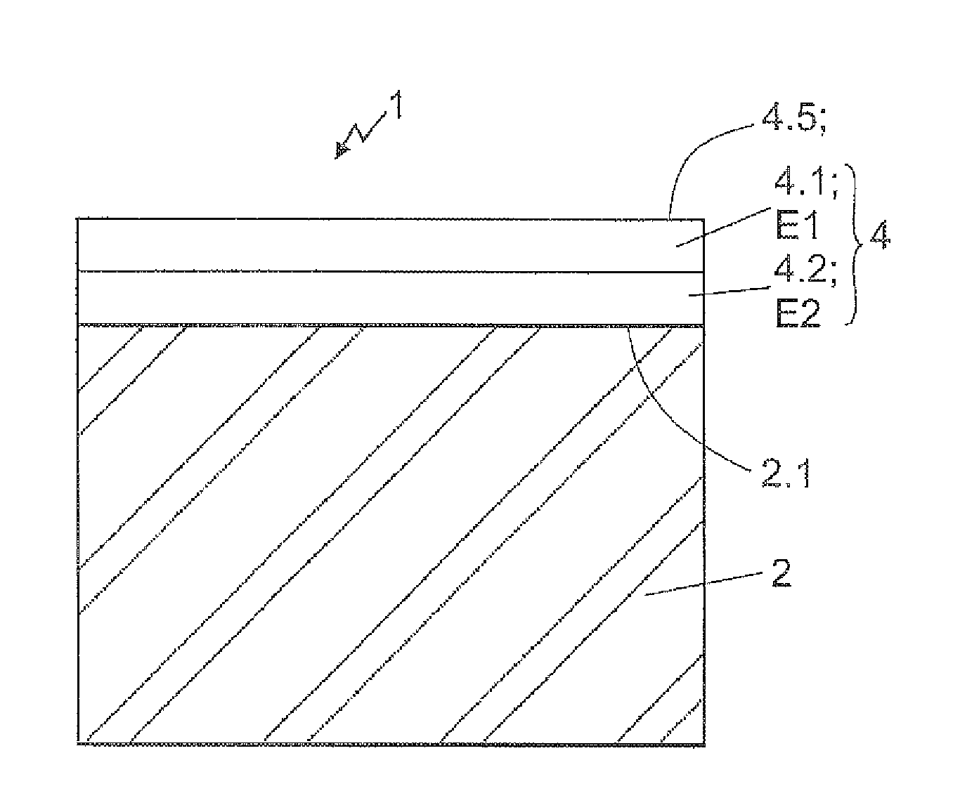
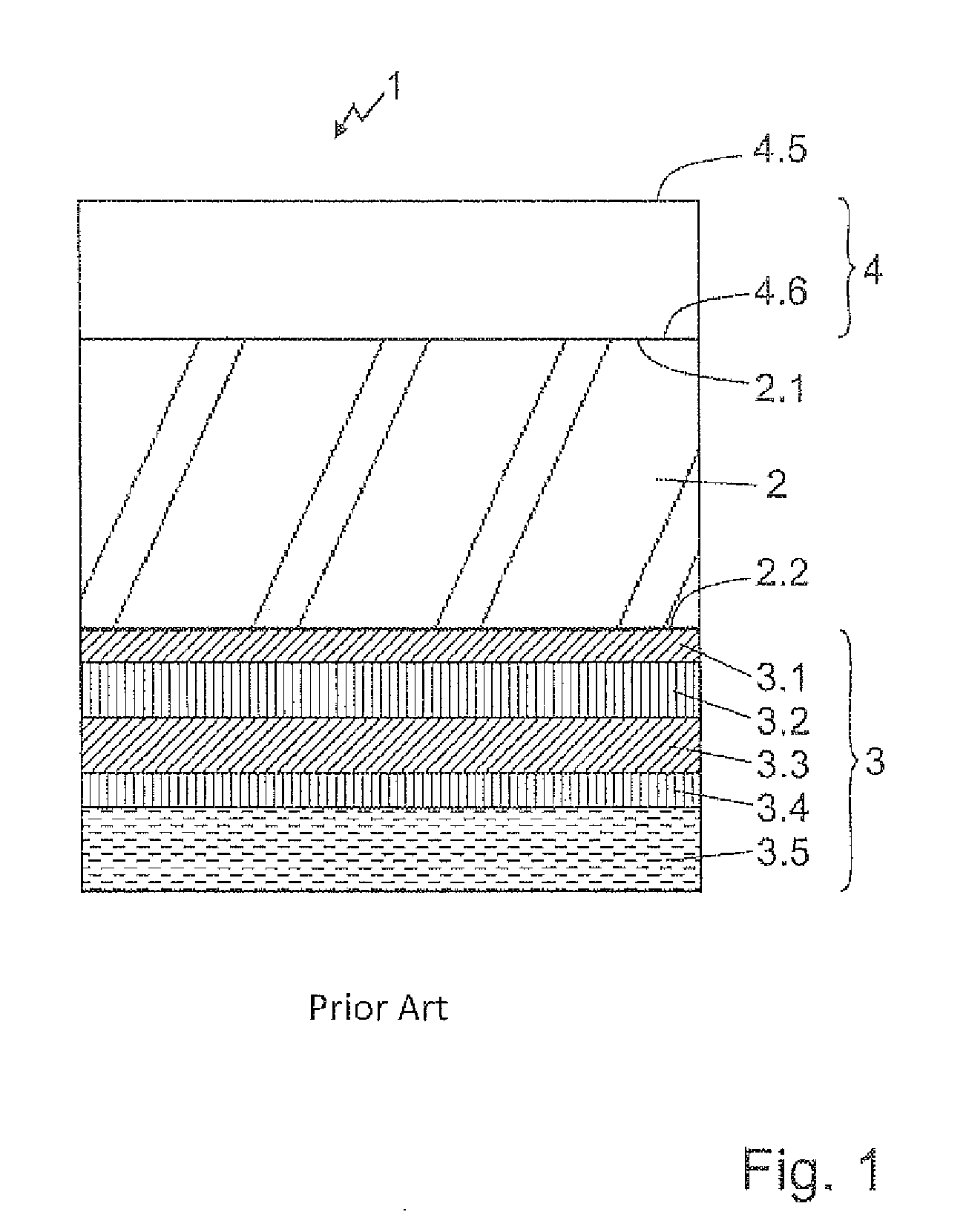
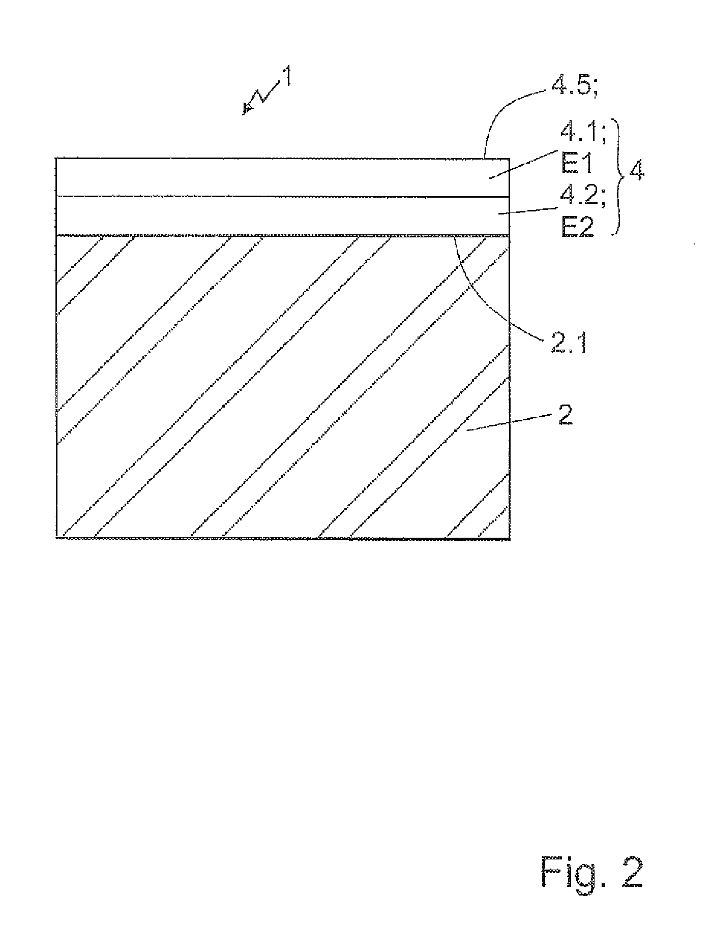
[0045]Optical IR components 1 according to the prior art and optical components 1 according to the invention both have a substrate 2 and a DLC coating 4 as essential components. In further embodiments, they can also have an antireflection coating 3 (also referred to as AR coating 3 for the sake of brevity).

[0046]In the construction of a prior-art optical IR component 1 which is shown schematically in FIG. 1, a DLC coating 4 is arranged on an outer surface 2.1 of the substrate 2 as an individual layer. An inner surface 4.6 of the DLC coating 4 is in direct contact with the outer surface 2.1 of the substrate 2. An outer surface 4.5 of the DLC coating 4 closes off the optical IR component 1 from an environment. The outer surface 4.5 is directly exposed to active environmental influences such as rain, wind or radiation. An AR coating 3 which is formed in this instance, for example, from a sequence of a first layer 3.1 to a fifth layer 3.5 of the AR coating 3 is arranged on an inner surf...


PUM

PropertyMeasurementUnit
wavelength rangeaaaaaaaaaa
wavelengthaaaaaaaaaa

Abstract

A multispectral optical IR component with a hybrid coating DLC coating and an antireflection coating. The DLC coating has at least an outer layer with a first modulus of elasticity and an inner layer with a second modulus of elasticity which are arranged one above the other on the antireflection coating. The value of the first modulus of elasticity is greater than the value of the second modulus of elasticity. There is a transmissivity to IR radiation of at least 80% over a first determined wavelength range and over a second determined wavelength range. The first determined wavelength range lies in the range of mid-wavelength IR radiation, and the second determined wavelength range lies in the range of long-wavelength IR radiation.

Description

RELATED APPLICATIONS[0001]The present application is a U.S. National Stage application of International PCT Application No. PCT / DE2013 / 100184 filed on May 17, 2013 which claims priority benefit of German Application No. DE 10 2012 010 291.7 filed on May 18, 2012, the contents of each are incorporated by reference in their entirety.BACKGROUND OF THE INVENTION[0002]The invention is directed to a DLC coating and optical IR components with a DLC coating as is known generically from U.S. Pat. No. 4,995,684 A.[0003]Optical IR components in systems which are designed for use with infrared radiation must be able to transmit images and signals of high and consistent quality with long-term stability particularly when they are used in installations for measuring, testing or monitoring. By optical IR components is meant hereinafter all elements provided for applications in wavelength ranges of infrared radiation. Optical IR components may be, for example, optical lenses, mirrors, filters, beams...

Claims


Application Information

Patent Timeline
Patent Type & Authority Applications(United States)
IPC IPC(8): G02B1/10G02B1/11
CPCG02B1/11G02B1/105C23C14/06C23C16/02C23C16/26G02B1/113C23C28/046C23C28/044G02B1/14
Inventor GITTLER, ELVIRAWAGNER, TINODEGEL, MICHAELMAUSHAKE, PETERSERWAZI, MARCUS
Owner JENOPTIK OPTICAL SYST
Why Eureka
Try Eureka