Microfluidic device and related methods

a microfluidic device and microfluidic technology, applied in the field of microfluidic devices, can solve the problems of inability to simulate complex, multi-component, and complex cells in vitro, and achieve the effects of increasing cell growth, decreasing cell growth, and increasing cell growth

Inactive Publication Date: 2015-04-23
MAINE INST FOR HUMAN GENETICS & HEALTH +1
View PDF1 Cites 14 Cited by
  • Summary
  • Abstract
  • Description
  • Claims
  • Application Information

AI Technical Summary

Problems solved by technology

Although the importance of gradients in biology and physics is well known, how cells respond to them is, unfortunately, not as well known due primarily to the overwhelming challenge to quantify or even detect gradients in vivo.
However, simulating complex, multicomponent, and dynamic gradients in vitro still remains difficult.
The results have been encouraging, but the technique is cumbersome to implement and extremely limited in application.
Unfortunately, this and similar techniques produce gradients that degrade with time making them generally unsuited to the long term studies mandated by axon growth, cellular development, or cellular taxis.
However, a serious drawback for these microfluidic gradients is that they require perturbing flows—something usually not experienced in vivo outside of the bloodstream and known to deleteriously affect the behavior of many cells, particularly neural growth (Walker, 2005) and cellular taxis.
Although immobilization techniques have proven quite useful, they, unfortunately, lack a certain biological reality.
It is a significant technical challenge to study cellular responses to in vivo gradients quantitatively, which requires knowledge of the actual spatial and temporal concentrations of chemical cues.
Although it is well accepted that cells respond to chemical gradients, how they respond is not well understood.
To address these issues, researchers have turned to in vitro systems, but simulating the complex in vivo environment, with multi-component or dynamic gradients remains difficult.
Moreover, although it is well accepted that exposure to environmental toxins, both natural and artificially imposed, will predispose a person to disease, the specifics such as dosage time, concentration, and most importantly what specific combination of toxins are required to induce a specific pathology remain unknown.
Individual gene variations may also dictate susceptibility to toxin exposures, thereby adding additional complexity.
Further, the use of pesticides and herbicides in forestry and the pulp and paper industry, combined with naturally occurring high rates of arsenic and radon, may have increased the risk for cancer in certain geographical areas.
Early detection is a universal challenge to disease treatment that is particularly relevant to people living in rural communities who are more likely to have long term toxin exposure, yet are less likely to obtain routine medial screenings.

Method used


Image

  • Microfluidic device and related methods
  • Microfluidic device and related methods
  • Microfluidic device and related methods

Examples


example 1

Microfluidic Device Materials and Methods Used

[0221]A. Optical Measurements

[0222]Optical measurements were performed using a Zeiss Axioplan 2 reflection microscope with fluorescence capabilities. Optical visualization of the diffusion profiles were demonstrated using simple organic dyes mixed with water to an appropriate absorbance and used directly. Fluorescence measurements were performed using fluorescein conjugated Bovine Serum Albumin, (BSA) from Molecular Probes with 6.2 fluoresceins per BSA molecule. The BSA was dissolved in phosphate buffered saline (PBS) to a concentration of 0.4 mg / ml and introduced directly in the fluidic microchannels. Agarose (Bacto-Agar, Difco Labs, 0.5% to 1% in DI water) or Matrigel (BD Bioscience, Reduced Growth Factor, LDEV-free) was used as the growth / diffusion medium for the microsystem and test devices.

[0223]B. Computer Simulations

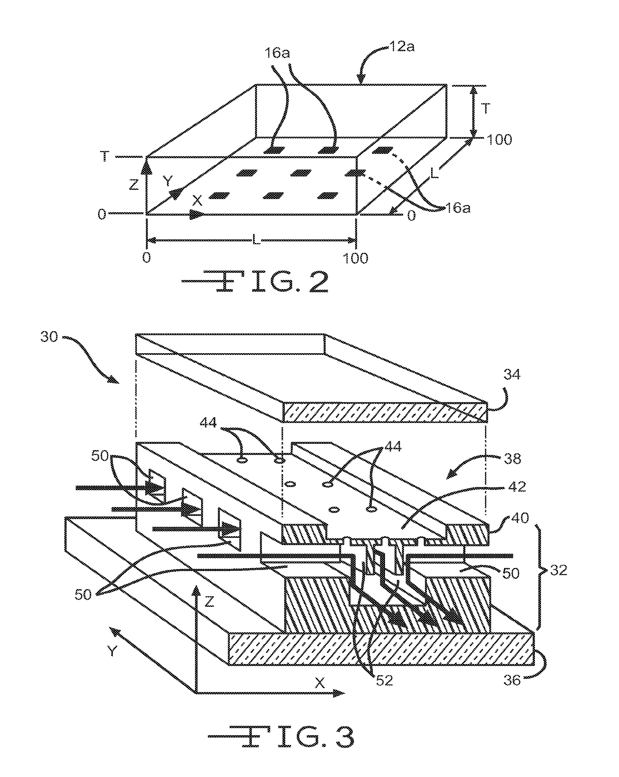
[0224]Concentration profiles were calculated by finite element volume analysis on an L×L×T (x,y,z) rectangular latti...

example 2

Microfluidic Device Results

[0231]A. Computer Simulations

[0232]Diffusion is the driving force behind the formation of concentration profiles, and the fundamental equations driving diffusion are Fick's first and second laws.

Ji=-Di∇CiEq1∂Ci(x,y,z,t)∂t=-Di∇2Ci(x,y,z,t)Eq2

[0233]Where Ji is the flux and Di is the diffusion coefficient or diffusivity of species i, Ci(x,y,z,t) is the concentration of i at point (x,y,z,t) and ∇□ is the del operator (Bard, 2001). A finite element simulation, FIG. 5, for a 5×5 array of diffusion ports spaced 25 lattice units apart, Δl=25, was performed with the center diffusion port as a single concentration source with a normalized concentration of 100, Ci(50,50,0,t)=100, and the remaining diffusion ports held at zero. FIG. 5 shows the resulting, steady-state, 2D concentration profile on the xy plane at z=0, i.e. the concentration profile at (x,y,0,t=∞). The source diffusion port is clearly seen as the peak at the center of the field, while the sink diffusion...

example 3

Microfluidic Device Experimental Verification

[0239]To experimentally validate the results of the diffusion simulations and demonstrate the power and versatility of the diffusion microsystem to control both temporal and spatial diffusion profiles, the device shown in FIG. 4(b) was characterized experimentally by addressing each microfluidic channel with a differently colored organic dye. There are eight, 20 μm×20 μm diffusion ports 104 spaced equally along the length of each microchannel, although for ease of illustration only 4 are shown in FIG. 4(b). The separation between microchannels is approximately 1 mm. FIG. 9(a) shows the microdevice 100 with a different color dye loaded in each microchannel 102a, 102b, 102c and 102d at the beginning of the experiment before diffusion profiles have become established, i.e. t=0. Channel 102a was filled with blue die, channel 102b was filled with green die, channel 102c was filled with orange die, and channel 102d was filled with red die. FIG....


PUM

PropertyMeasurementUnit
flow rateaaaaaaaaaa
volumesaaaaaaaaaa
volumesaaaaaaaaaa

Abstract

A combinatorial microenvironment generator is configured for the generation of arbitrary, user-defined, steady-state, concentration gradients with negligible to no flow through the growth medium to perturb diffusion gradients or cellular growth. More importantly, the absolute concentrations and / or gradients can be dynamically altered upon request both spatially and temporally to impose tailored concentration fields for in-situ stimulus studies. Here, diffusion occurs via an array of ports, each of which can be an independently controlled source / sink. Together, the array of ports establishes a user-defined, 3D concentration profile. Useful methods related to this device are also provided.

Description

CROSS-REFERENCE TO RELATED APPLICATIONS[0001]This application claims the benefit of U.S. Provisional Application No. 61 / 157,439 filed Mar. 4, 2009, the disclosure of which is incorporated herein by reference.STATEMENT OF FEDERAL SPONSORSHIP[0002]This invention was not funded by the United States government.FIELD OF THE INVENTION[0003]The present invention pertains generally to the field of biology, chemistry and physics. This invention pertains to a microfluidic device and methods which can produce user-defined concentrations and / or concentration gradients within an in vitro medium with temporal and spatial control. The resulting microenvironment can produce complex conditions without the presence of potentially perturbating fluid flow. The instrument is capable of indefinitely maintaining concentration profiles, which, in turn provides a variety of opportunities for use.BACKGROUND OF THE INVENTION[0004]In many biological and physical systems, information is encoded through gradient...

Claims


Application Information

Patent Timeline
Patent Type & Authority Applications(United States)
IPC IPC(8): C12M1/34B01L3/00C12M1/00G01N33/50C12M3/06
CPCC12M41/46G01N33/5008C12M41/32C12M23/16C12M29/10G01N2500/10B01L2300/0867B01L2300/0829B01L2400/084B01L2200/0694B01L3/502776B01D61/00C12M23/12C12M25/14C12Q1/025G01N35/1002G01N2035/00237Y10T29/49826
Inventor COLLINS, SCOTT D.SMITH, ROSEMARY L.HOCK, JANET M.
Owner MAINE INST FOR HUMAN GENETICS & HEALTH
Why Eureka
Try Eureka