Inline rheology/viscosity, density, and flow rate measurement

a flow rate and density technology, applied in specific gravity measurement, instruments, nuclear magnetic resonance analysis, etc., can solve the problems of difficult to measure viscosity on-line, unsuitable for fluids that may contain particles or sticky deposits, and generally used instruments for making measurements. , to achieve the effect of reducing the sensitivity to flow-related frictional effects, reducing pumping energy, and reducing frictional losses

Active Publication Date: 2015-05-07
ASPECT IMAGING
View PDF15 Cites 4 Cited by
  • Summary
  • Abstract
  • Description
  • Claims
  • Application Information

AI Technical Summary

Benefits of technology

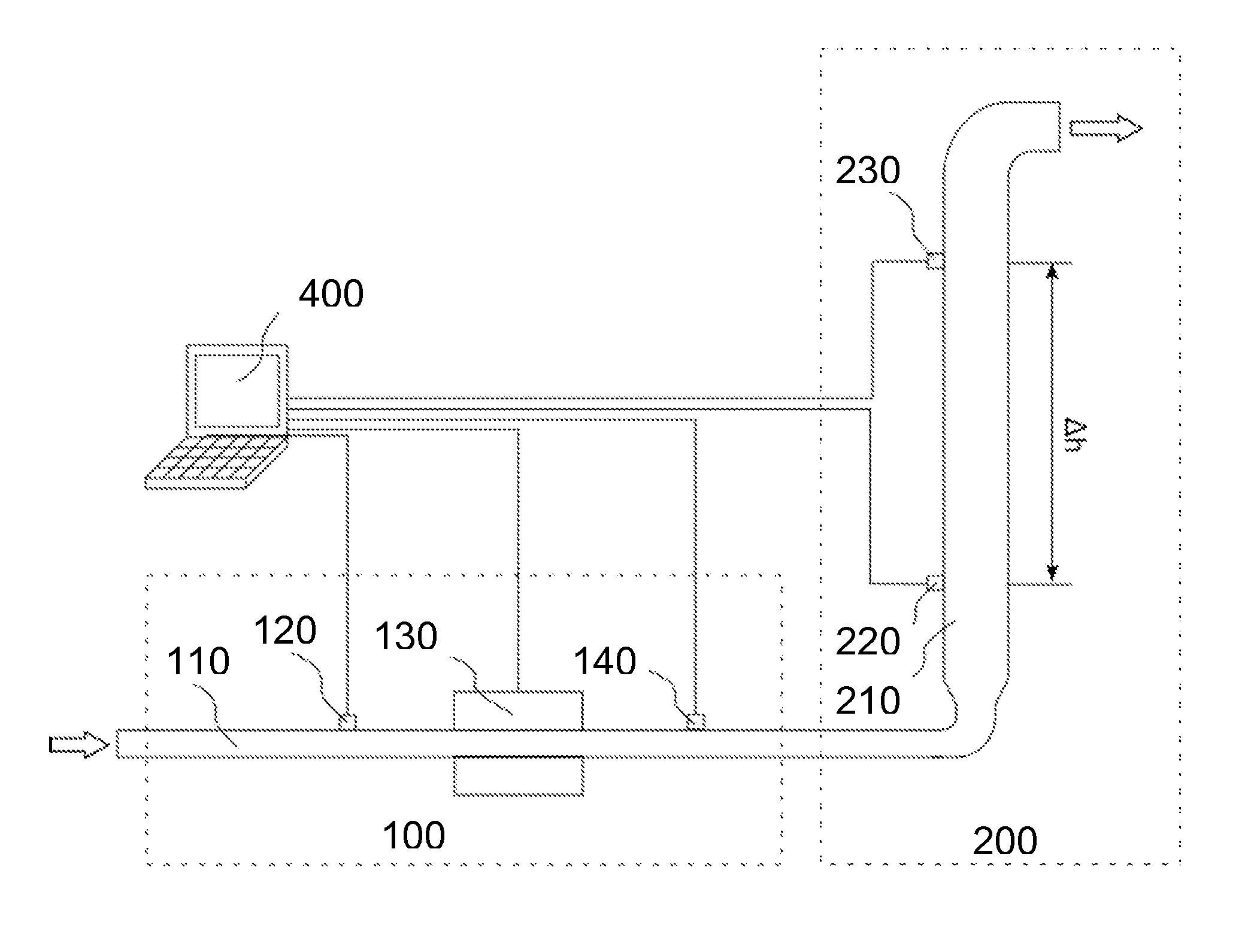
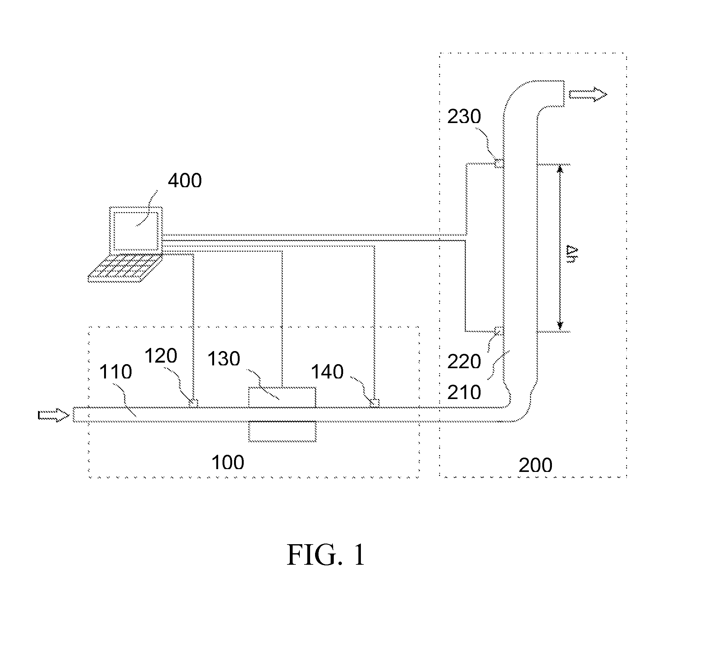
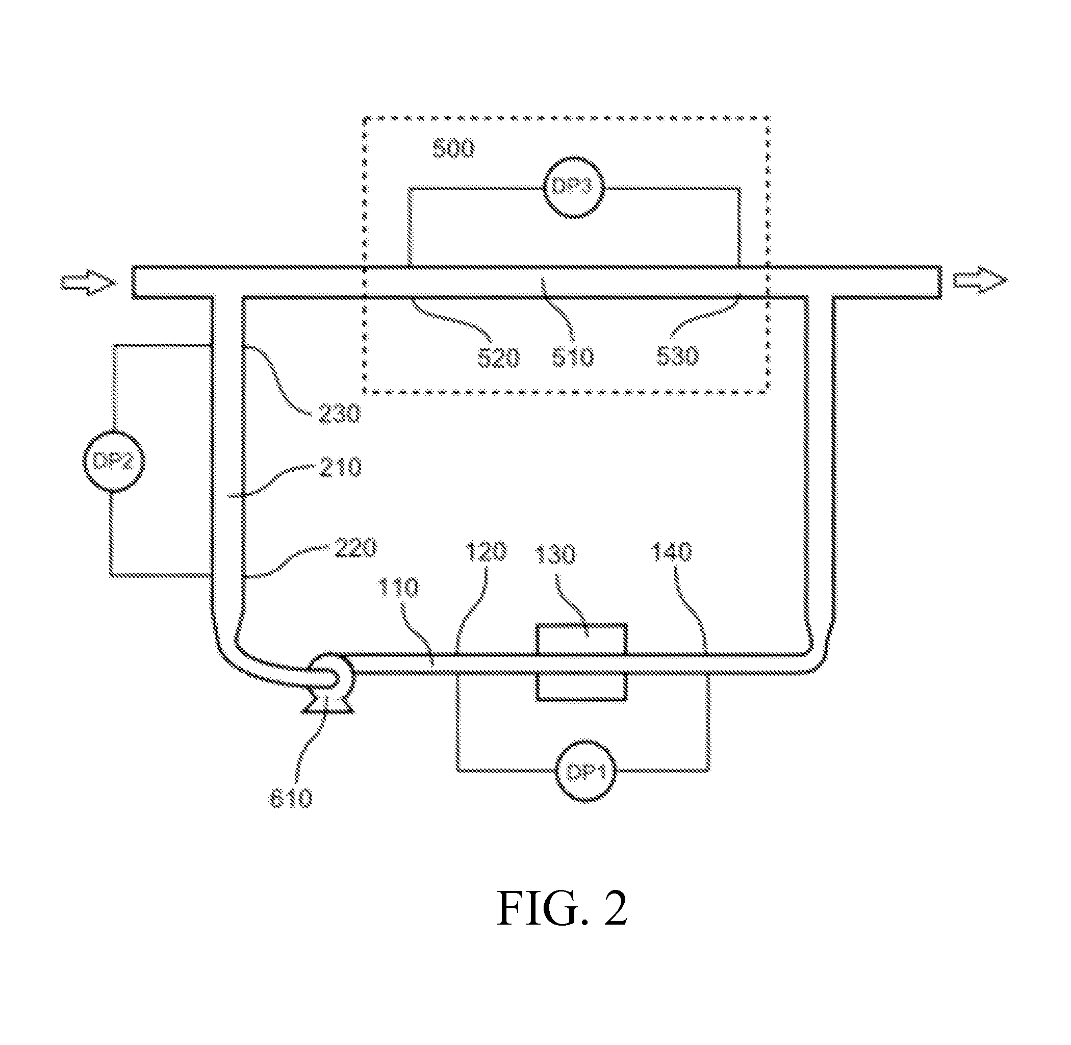
[0007]The system herein disclosed is designed to meet this long-felt need. The system comprises a horizontal tube for measurement of rheology and at least one vertical tube for measurement of density. Due to the rheology already having been measured in the horizontal tube, the tube or tubes that make up the vertical density measurement section may be of larger diameter that the horizontal tubes. Advantages of having larger diameter tubes in the vertical section include reduced pumping energy due to smaller frictional losses and lower sensitivity to flow-related frictional effects in the vertical tube, making the density measurements more precise and less susceptible to errors due to flow fluctuations. Having a horizontal tube (i.e. in the section of the system that measures rheology) of smaller diameter has the advantage that it provides a strong (and hence easily detectable) signal for measurement of pressure drop even over a short distance, and that it requires smaller, less costly imaging equipment; for example, the costs of MRI magnets increase nonlinearly with bore size.

Problems solved by technology

Control and monitoring of processes involving the flow through tubes of fluids that may be of complex rheology is an important problem in such diverse industrial settings as preparation and processing of food, manufacture of personal care products, oil exploration, extraction, and production, production of coatings, and biotechnology.
Viscosity in particular is difficult to measure on-line, as particulate matter in the fluid tends to interfere with the operation of most conventional viscometers, and many fluids of interest have viscosities that depend on the shear rate or shear rate history and hence cannot be described by a single-valued viscosity.
Construction of rheograms (flow curves) for such fluids requires more sophisticated instrumentation than a simple viscometer, but the instruments generally used for making the measurements needed to construct rheograms, which generally contain narrow gaps or vibrating elements, are unsuitable for fluids that may contain particles or sticky deposits.
These instruments only measure density, however, and do not provide information about rheology or flow rate.
Furthermore, the methods disclosed in these patents require that all of the tubes be of the same diameter, since the rheology of the fluids is unknown.
These instruments, while multi-parametric, do not measure rheology, and are susceptible to errors if the mass of the vibrating element changes due to solid deposits.
In addition, at very low flow rates, these instruments have large errors, reducing the range of flow rates that can be measured by a single instrument; the instrument must be selected to match the process conditions and a larger or smaller instrument may be needed if the conditions change.
These systems can measure rheology and flow rate even for difficult systems containing large particles, and a single instrument can be calibrated electronically to cover a wide range of flow rates, but they cannot measure fluid density.

Method used


Image

  • Inline rheology/viscosity, density, and flow rate measurement
  • Inline rheology/viscosity, density, and flow rate measurement
  • Inline rheology/viscosity, density, and flow rate measurement

Examples


Embodiment Construction

[0043]In the following description, various aspects of the invention will be described. For the purposes of explanation, specific details are set forth in order to provide a thorough understanding of the invention. It will be apparent to one skilled in the art that there are other embodiments of the invention that differ in details without affecting the essential nature thereof. Therefore the invention is not limited by that which is illustrated in the figure and described in the specification, but only as indicated in the accompanying claims, with the proper scope determined only by the broadest interpretation of said claims.

[0044]As used herein, the term “NMR spectrometer” refers to any device that uses nuclear magnetic resonance to obtain information about a test substance.

[0045]As used herein, the term “imaging NMR spectrometer” refers to an NMR spectrometer that comprises means for providing a homogeneous magnetic field, at least one radio frequency coil, and magnetic gradient ...


PUM

PropertyMeasurementUnit
flow rateaaaaaaaaaa
densityaaaaaaaaaa
rheologyaaaaaaaaaa

Abstract

A system of performing inline measurements of flow rate, density, and rheology of a flowing fluid. The system includes a rheology measurement subsystem, a density measurement subsystem, and a pressure sensor for measuring the pressure of the test fluid within the vertical tube at a location y2 downstream from y1 and displaced vertically from y1 by a distance Δh.

Description

FIELD OF THE INVENTION[0001]The invention disclosed herein is related in general to means and methods for measuring physical properties of flowing fluids. Specifically, it is related to means and methods for performing inline multiple-parameter measurements.BACKGROUND OF THE INVENTION[0002]Control and monitoring of processes involving the flow through tubes of fluids that may be of complex rheology is an important problem in such diverse industrial settings as preparation and processing of food, manufacture of personal care products, oil exploration, extraction, and production, production of coatings, and biotechnology. Ideally, measurements should be made non-invasively and in real time so that defects or variations in quality can quickly be identified and corrected, and all of the parameters of interest would be obtained by a single measurement device. Among the fluid parameters of interest are the flow rate, density, and viscosity. Viscosity in particular is difficult to measure ...

Claims


Application Information

Patent Timeline
Patent Type & Authority Applications(United States)
IPC IPC(8): G01N9/26G01N11/04
CPCG01N11/04G01N9/26G01N24/085G01R33/56308G01N24/08G01N11/08
Inventor TOZZI, EMILIO JAVIERRAPOPORT, URI
Owner ASPECT IMAGING
Why Eureka
Try Eureka