Method and apparatus for cleaning jet engines

a jet engine and jet engine technology, applied in the direction of machines/engines, cleaning using liquids, transportation and packaging, etc., can solve the problems of reducing engine efficiency and jet engine contamination, and achieve the effect of optimizing the cleaning operation and minimizing the likelihood of operator error

Active Publication Date: 2015-05-07
ROCHEM TECHN SERVICES HLDG
View PDF2 Cites 27 Cited by
  • Summary
  • Abstract
  • Description
  • Claims
  • Application Information

AI Technical Summary

Benefits of technology

[0014]The specific number and positioning of the spray outlets about the ring ensure uniform root to tip cleaning of both rotating and stationary airfoils of the core compressor and the main fan, while the physical size of the ring ensures compatibility with the inlet annulus of the core engine. Non-contact alignment means are provided to insure that the wash ring is positioned properly and centrally to the engine compressor and main fan. Thus, with the correct parameters established automatically by the system for the engine to be cleaned, the likelihood of operator error is minimized and the results of the cleaning operation maximized. The cart is fully s...

Problems solved by technology

Jet engines, and particularly the compressors of aircraft jet engines and helicopter turbo-shaft engines, are subject to contamination from the ingestion of general airborne pollution, as well as unburned hydrocarbons (soot), lubricating oil vapors etc., emanating from other aircraft engines when maneuvering around airports and on take-off and landing.
Such contamination can lower engine efficiency, lead to undesirable increases in exhaust gas temperature and in extreme cases can result in engine failure.
Cleaning of a jet engine helps to maintain its overall efficiency, as even moderately dirty engine can easily result in about a 0.5 to 1.5% increase in fuel consumption.
And given the prodigious amounts of jet fuel used on a daily basis and today's high fuel costs, keeping jet engines clean can directly affect an airline's bottom line.
On-the-wing hand-cleaning is almost totally ineffective because only the first few stages of the compressor are accessible by hand; most of the compressor remains uncleaned.
However, with the introduction of turbine cooling by compressor bleed air—now utilized in the vast majority of gas turb...

Method used


Image

  • Method and apparatus for cleaning jet engines
  • Method and apparatus for cleaning jet engines
  • Method and apparatus for cleaning jet engines

Examples


Embodiment Construction

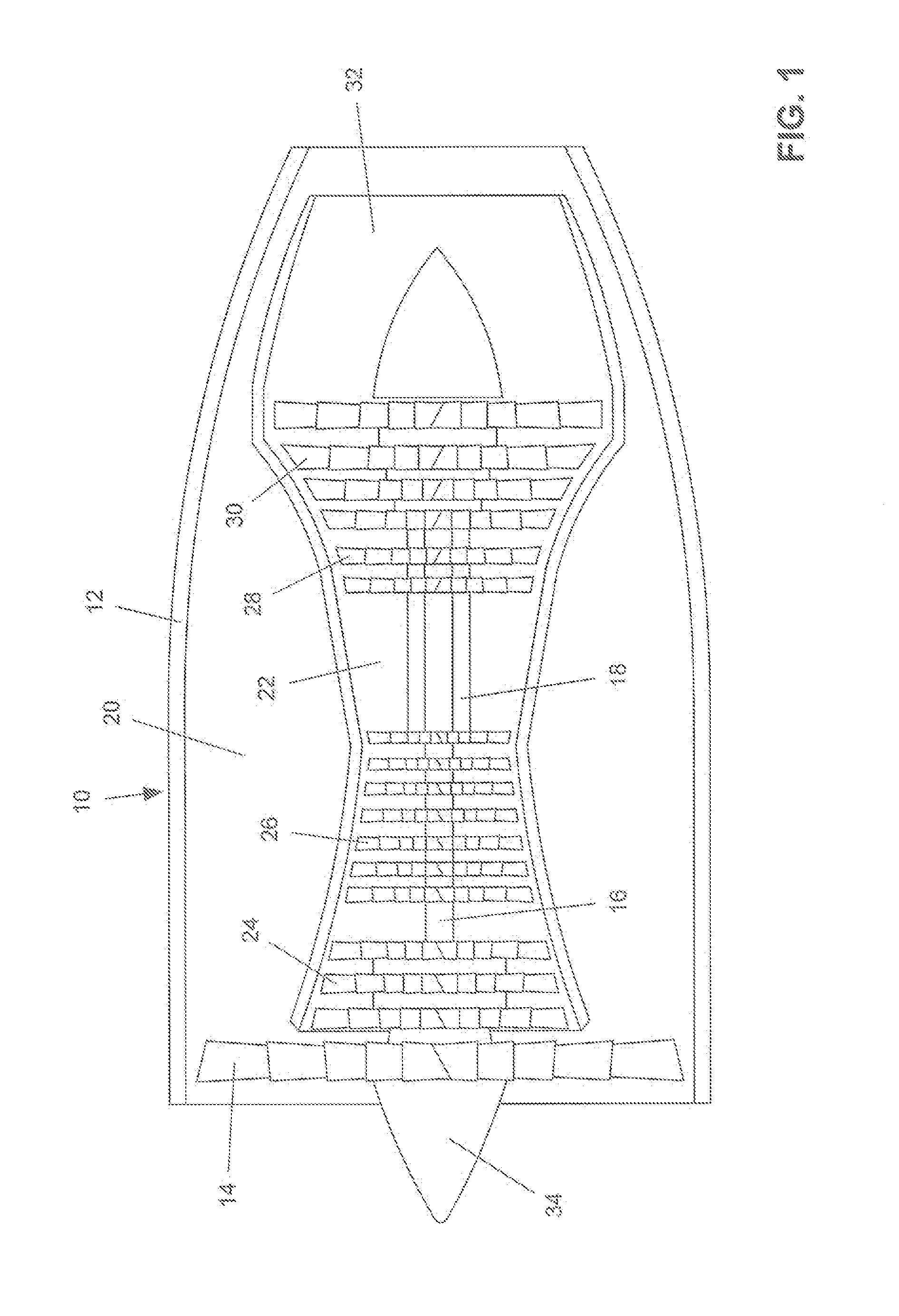
[0026]FIG. 1 is a diagrammatic representation of a turbofan jet engine 10, which is exemplary of a type of jet engine with which the present invention can be utilized. Engine cowling or nacelle 12 surrounds the operating elements of the engine, which include main turbofan 14 which is connected to low pressure shaft 16. With the engine in operation, the fan 14 directs a portion of the incoming air through low and high pressure compressor stages 24 and 26 into the engine's combustion chamber 22 and the remainder of the air into bypass duct 20. After passing through both the low and high pressure compressor stages 24 and 26 the combustion air is combined with jet fuel and ignited in the combustion chamber 22.

[0027]The hot combustion gasses travel rearwards, expanding through and driving high and low pressure turbine stages 28, 30, before exiting the engine through the exhaust assembly 32. The turbines 28 and 30 provide the rotational force for the main propulsion fart and core engine c...


PUM


Abstract

An apparatus for the cleaning of a turbine engine comprises a towable wash cart having a reservoir for cleaning fluid. The reservoir is connected through a pump system to a wash ring operatively mounted to the cart. The wash ring has a plurality of spray nozzles about its periphery arid positionably adjustable for directing an atomized spray of the cleaning fluid into an inlet of the engine. The cart and wash ring is aligned with the engine such that there is no physical contact between the wash ring and engine during the entirety of the cleaning process. While a preferred cleaning fluid is pure water, the reservoir may be segmented to carry a number of different cleaning solutions, which can be mixed in a manifold of the pump system as may be desired for a particular cleaning process. The reservoirs may be heated and insulated to maintain the cleaning solutions at an elevated temperature. A sluice cart may be provided to collect cleaning fluid draining fur the engine for delivery to a collection tank on the wash cart.

Description

[0001]The present invention relates to a method and apparatus primarily for the cleaning of aircraft turbofan or turbojet engines of any kind. The system may also be utilized tor the cleaning of turbo-shaft engines of helicopters as well as many types of aero-derivative industrial gas turbines.BACKGROUND OF THE INVENTION[0002]Jet engines, and particularly the compressors of aircraft jet engines and helicopter turbo-shaft engines, are subject to contamination from the ingestion of general airborne pollution, as well as unburned hydrocarbons (soot), lubricating oil vapors etc., emanating from other aircraft engines when maneuvering around airports and on take-off and landing. Such contamination can lower engine efficiency, lead to undesirable increases in exhaust gas temperature and in extreme cases can result in engine failure.[0003]Accordingly, to maintain engine fuel efficiency and power output, as well as the avoidance of potential engine failure, the cleaning of the gas path of j...

Claims


Application Information

Patent Timeline
IPC IPC(8): B64F5/00B08B9/00B08B3/02
CPCB64F5/0018B08B9/00B08B3/02F01D25/002Y02T50/60
Inventor MCDERMOTT, PETER
Owner ROCHEM TECHN SERVICES HLDG
Why Eureka
Try Eureka