Super-hydrophobic surfaces and methods for producing super-hydrophobic surfaces
- Summary
- Abstract
- Description
- Claims
- Application Information
AI Technical Summary
Benefits of technology
Problems solved by technology
Method used
Image

Examples
example 1
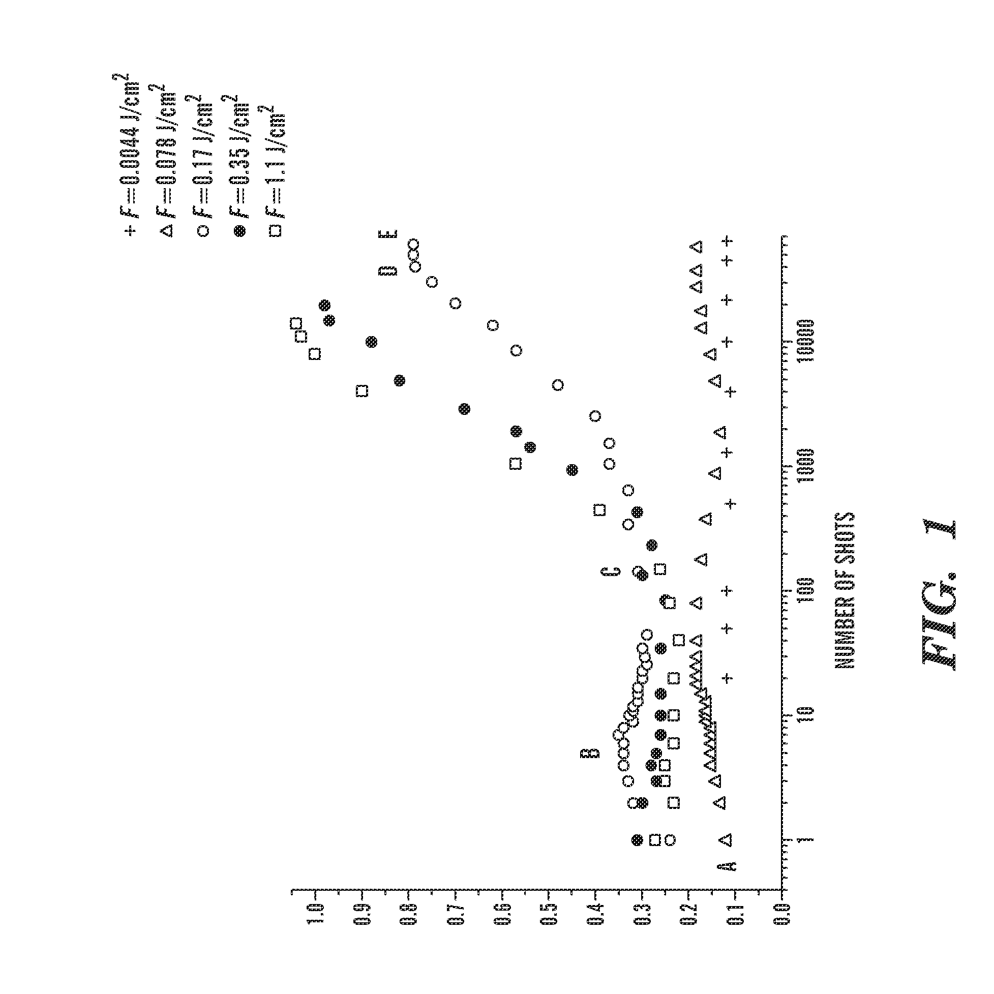
[0128]Experiments in support of embodiments of the invention have demonstrated that a significant amount of residual thermal energy is deposited in metal samples following multi-shot femtosecond laser ablation. Traditionally, it was commonly believed that one of the most important advantages of femtosecond laser ablation is that the energy deposited by ultrashort laser pulses does not have enough time to move into the bulk sample; therefore, the residual thermal energy remaining in the bulk sample should be negligible. In contrast to this, a significant enhancement in laser light absorption was observed recently by the inventors following ablation. To understand the physical mechanisms of laser energy absorption, the change in absorptance of gold due to structural modifications following multi-shot femtosecond laser ablation was directly measured. The measured data indicates that there is a significant absorption enhancement due to nanostructuring in addition to the known mechanisms...
example 2
[0141]In this Example, a comparative study of residual thermal effects in aluminum following fs laser ablation was performed. At laser fluences above the ablation threshold where plasmas are produced and at a sufficiently high ambient gas pressure, an enhanced coupling of pulsed laser energy into the sample occurs. Furthermore, in contrast to the conventional understanding that residual thermal energy is negligible in fs-laser ablation, up to 70% of the incident pulse energy can be retained in the sample following single-pulse fs-laser ablation in 1-atm air. The major factors influencing thermal energy coupling to the sample are the laser fluence and ambient gas pressure. Residual thermal energy deposition decreases with reducing ambient gas pressure.
[0142]Laser ablation using femtosecond (fs) laser pulses has numerous applications in the field of materials processing and machining and, nanotechnology. Comparative studies have demonstrated that femtosecond laser ablation has advanta...
example 3
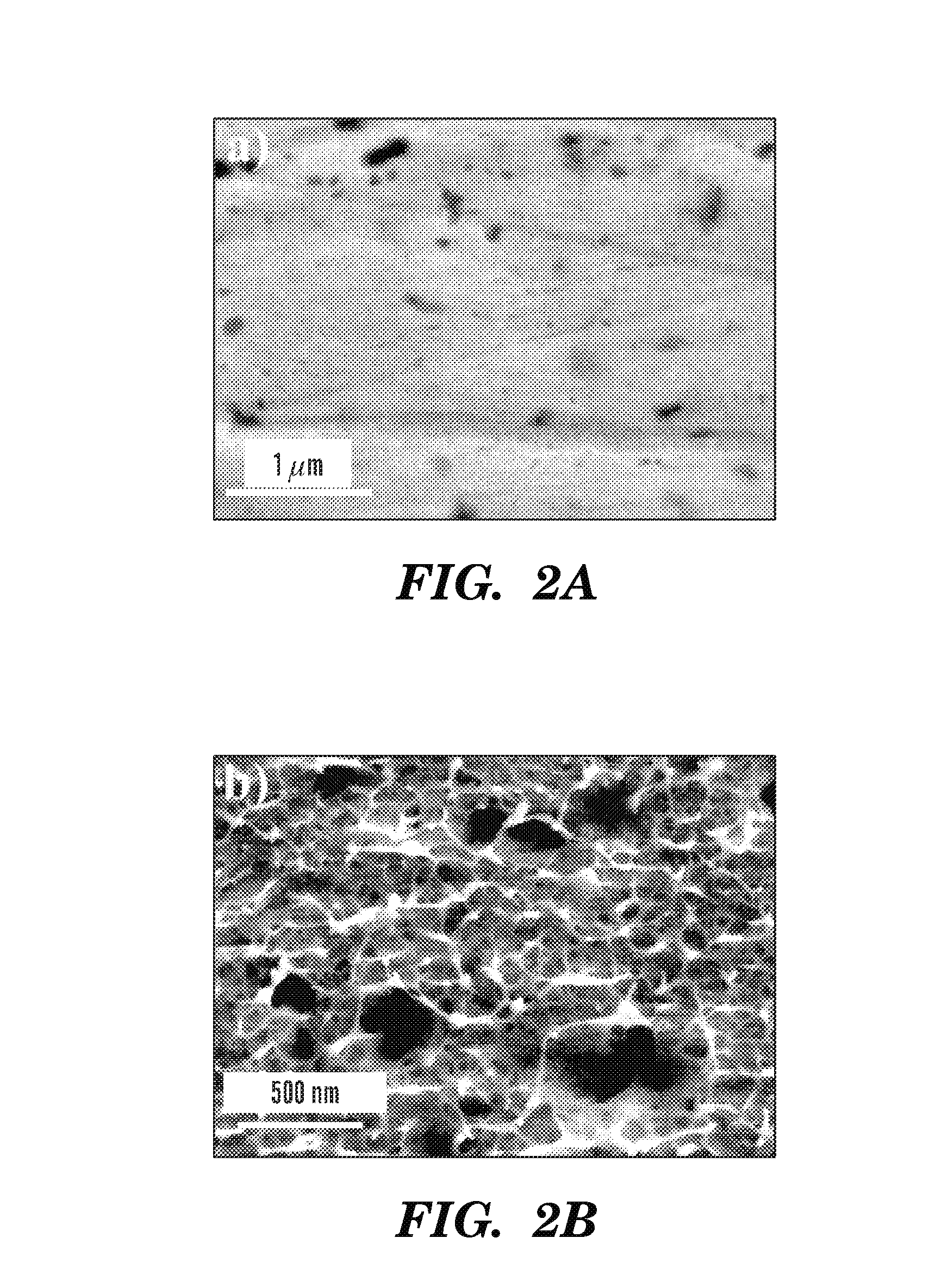
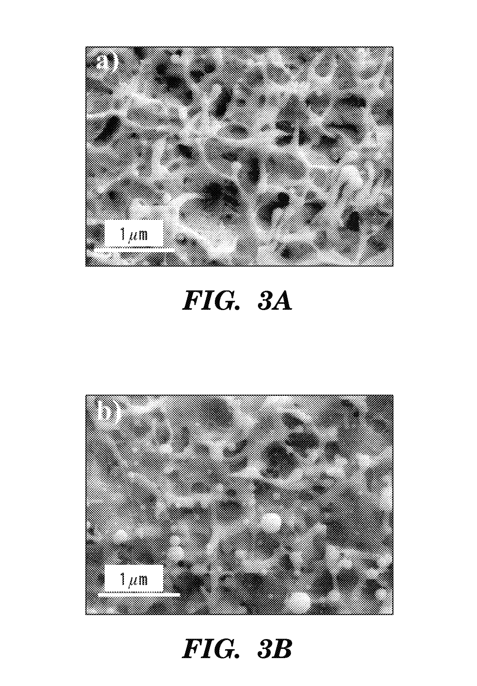
[0155]Unique properties of nanomaterials have been extensively studied in the past and various nanostructures have found numerous applications in optics including enhanced x-ray emission and enhanced absorption in intense light-matter interaction, and optical biosensing, to name a few. Direct surface nanostructuring (i.e., not from ablated plume deposition) may be used in a number of technological applications, for example, manipulation of optical properties of solids, catalysts, dental implants, etc. We performed a detailed study of the morphology of surface nanomodifications produced on bulk metals using a femtosecond laser ablation technique embodied herein. The effects of laser fluence and number of applied pulses on the generated surface nanostructures were studied with a scanning electron microscope (SEM). According to an aspect, a set of optimal laser irradiation conditions for metal surface nanostructuring is disclosed.
[0156]In our experiment, we used an amplified Ti:sapphir...
PUM
| Property | Measurement | Unit |
|---|---|---|
| Length | aaaaa | aaaaa |
| Length | aaaaa | aaaaa |
| Length | aaaaa | aaaaa |
Abstract
Description
Claims
Application Information
 - Generate Ideas
- Intellectual Property
- Life Sciences
- Materials
- Tech Scout
- Unparalleled Data Quality
- Higher Quality Content
- 60% Fewer Hallucinations
Browse by: Latest US Patents, China's latest patents, Technical Efficacy Thesaurus, Application Domain, Technology Topic, Popular Technical Reports.
© 2025 PatSnap. All rights reserved.Legal|Privacy policy|Modern Slavery Act Transparency Statement|Sitemap|About US| Contact US: help@patsnap.com