Separation membrane unit and method for using the same to produce fresh water

a separation membrane and membrane technology, applied in membrane technology, water treatment multi-stage treatment, membranes, etc., can solve the problems of reducing the flushing effect of the membrane surface, contaminating the membrane surface, and causing fouling, and achieve the effect of balancing the separation membrane, high operation rate, and effective prevention of fouling

Inactive Publication Date: 2015-05-28
TORAY IND INC
View PDF0 Cites 20 Cited by
  • Summary
  • Abstract
  • Description
  • Claims
  • Application Information

AI Technical Summary

Benefits of technology

[0023]In the present invention, separation membrane elements preferably constitute at least two subunits; the intermediate concentrated water discharged from the first subunit group (N) is fed to the other subunit group (M) in the opposite feed direction; and the separation membrane subunits that constitute the subunit group (N) to which raw water is first fed are sequentially changed, thereby allowing inhibition of contamination of the separation membrane unit with no or little need for downtime of the separation membrane unit, allowing the use of the separation membranes to be balanced, and allowing effective prevention of fouling while maintaining a high operation rate. Thus, the present invention can provide a separation membrane unit that prevents contamination of the separation membrane unit using spiral-wound membrane elements and that fully exploits the performance of the separation membranes while reducing maintenance time and labor, and a method for using such unit to produce fresh water.

Problems solved by technology

For efficient operation of such separation membrane, contamination of the membrane surface, which is called fouling, is the most significant problem.
However, if the pretreatment is insufficient and / or a large amount of impurities are contained, invasion of materials that cause fouling into the separation membrane is often not prevented.
And, in the case of desalination of seawater, due to osmotic pressure, the first separation membrane element exhibits high permeation flux, because the element receives less concentrate stream, and tends to deposit foulants on the membrane surface, thereby promoting fouling.
On the contrary, a later separation membrane element has the property of receiving water-to-be-treated at a lower flow rate due to permeation through a prior element, and thus producing reduced flushing effect on the membrane surface, so foulants deposited on the membrane surface are difficult to remove from the membrane surface.
However, these methods usually requires shutdown for removing foulants and requires maintenance time and labor, and thus there has existed a need for more efficiently preventing fouling while maintaining longer operating time.

Method used


Image

  • Separation membrane unit and method for using the same to produce fresh water
  • Separation membrane unit and method for using the same to produce fresh water
  • Separation membrane unit and method for using the same to produce fresh water

Examples


Embodiment Construction

[0034]Now, embodiments of the present invention will be described with reference to the drawings, although the present invention is not limited to the embodiments illustrated in the drawings.

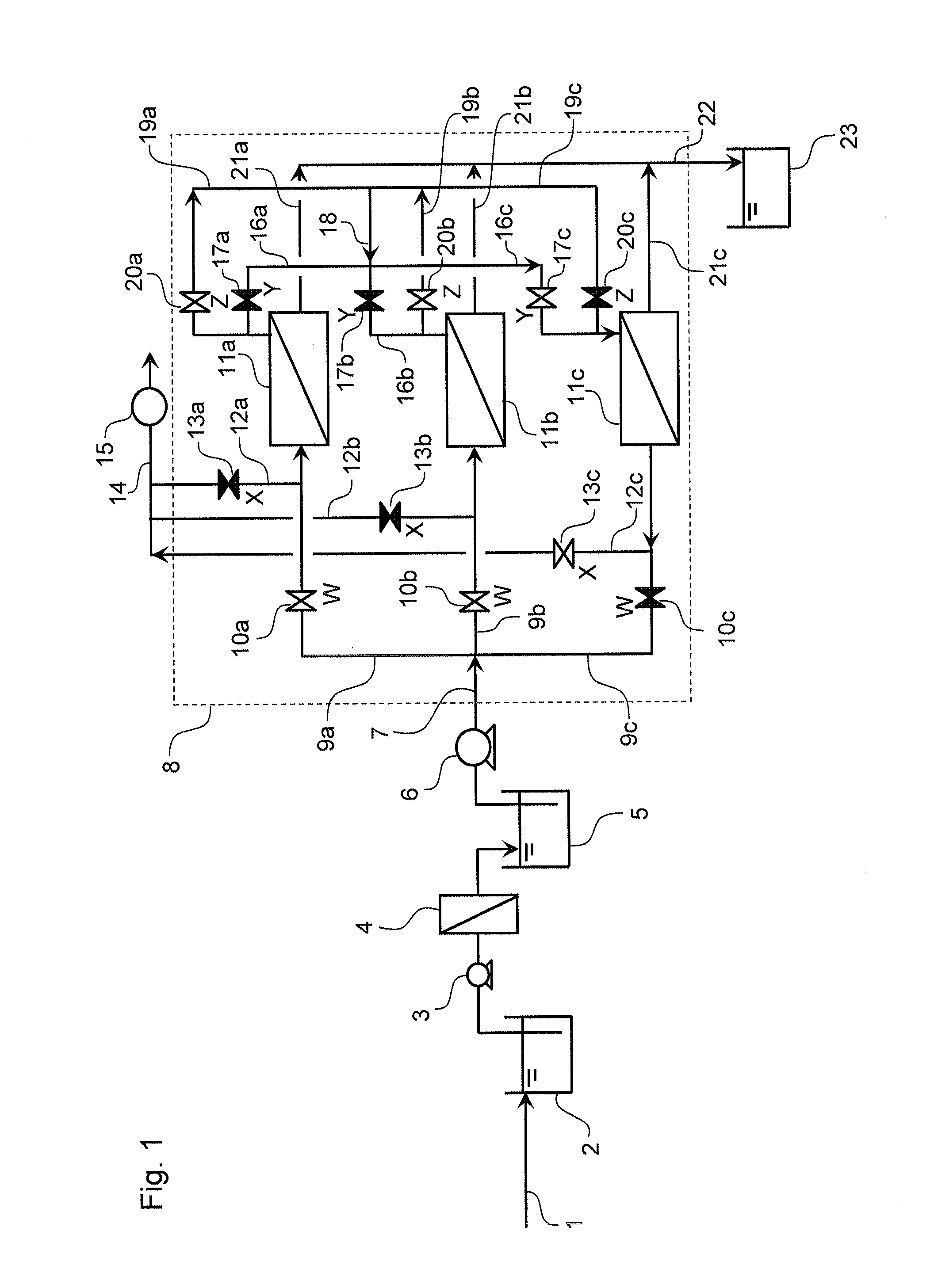
[0035]FIG. 1 is a flow diagram that illustrates an example of an embodiment of a device for producing fresh water, the device including the separation membrane unit of the present invention.

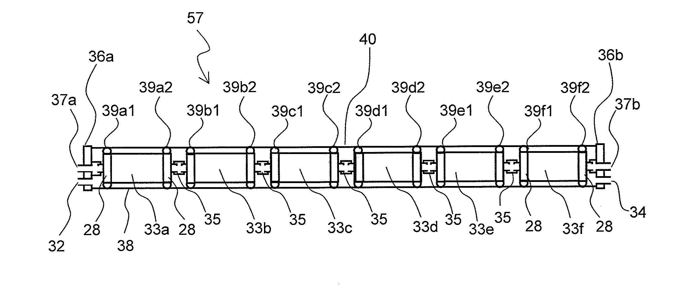
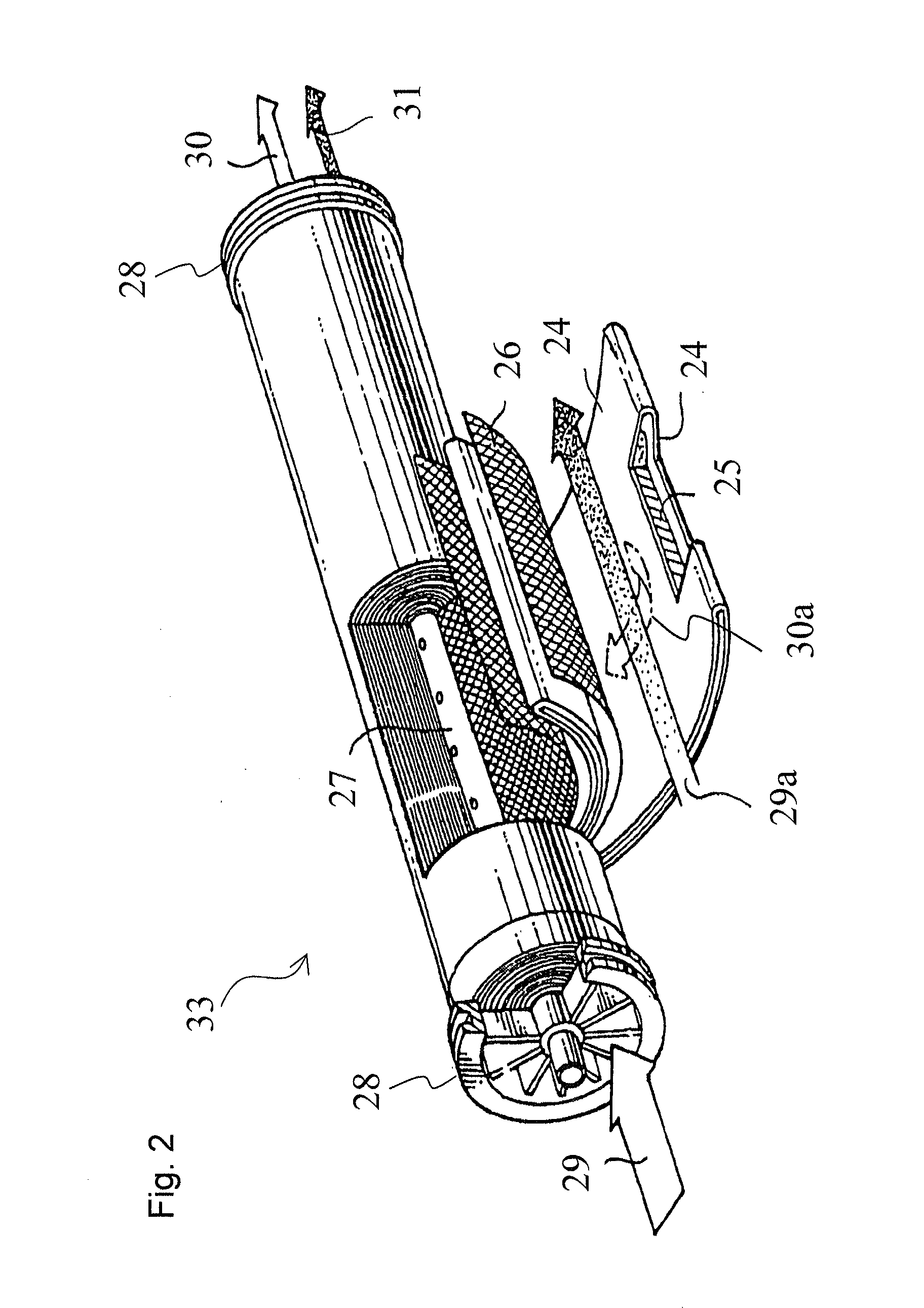
[0036]In FIG. 1, raw water 1 is fed to a raw water tank 2, and then pumped by a raw water feed pump 3. After treatment by a pretreatment unit 4, where necessary, the water is stored in a pretreated water tank 5. The pretreated water is fed through a main raw water line 7 to a separation membrane unit 8 by a pressure pump 6. The separation membrane unit 8 includes a plurality of separation membrane subunits 11a, 11b, and 11c, and each of the separation membrane subunits communicates with a raw water line A (9a, 9b, or 9c), a water discharge line B (12a, 12b, or 12c), a raw water line C (16a, 16b, or 16c), and ...


PUM

PropertyMeasurementUnit
thicknessaaaaaaaaaa
inner diameteraaaaaaaaaa
pressureaaaaaaaaaa

Abstract

There is provided a separation membrane unit wherein a plurality of separation membrane subunits (11a-c) communicate with raw water lines A (9a-c) that comprise raw water supply valves W (10a-c), water discharge lines B (12a-c) that comprise water discharge valves X (13a-c), raw water lines C (16a-c) that comprise first raw water communication valves Y (17a-c), raw water lines D (19a-c) that comprise second raw water communication valves Z (20a-c), and permeate water lines E (21a-c); and wherein the raw water lines A communicate with the water discharge lines B, the raw water lines C communicate with the raw water lines D, the raw water lines A communicate with a main raw water line 7, the water discharge lines B communicate with a main water discharge line 14, the raw water lines C and the raw water lines D communicate with a collection line 18, and the permeate water lines E communicate with a main permeate water line 22.

Description

CROSS REFERENCE TO RELATED APPLICATIONS[0001]This is the U.S. National Phase application of PCT / JP2013 / 065161, filed May 31, 2013, which claims priority to Japanese Patent Application No. 2012-126849, filed Jun. 4, 2012, the disclosures of each of these applications being incorporated herein by reference in their entireties for all purposes.FIELD OF THE INVENTION[0002]The present invention relates to a separation membrane unit for separating and removing a substance present in water-to-be-treated and a method for using such unit to produce fresh water.BACKGROUND OF THE INVENTION[0003]In recent years, fluid separation technologies using various separation membranes such as a gas separation membrane, a reverse osmosis membrane, a nanofiltration membrane, an ultrafiltration membrane, a microfiltration membrane, and the like have received attention as a fine and energy saving process, and the application of such technologies to treatment of various fluids has been promoted. For example,...

Claims


Application Information

Patent Timeline
Patent Type & Authority Applications(United States)
IPC IPC(8): C02F1/44B01D63/12
CPCC02F1/44B01D2319/02B01D63/12C02F2103/08C02F2301/08B01D63/106B01D2313/04Y02A20/131
Inventor TANIGUCHI, MASAHIDETOMIOKA, KAZUNORIMAEDA, TOMOHIRO
Owner TORAY IND INC
Why Eureka
Try Eureka