
Electronic component and manufacturing method therefor

a manufacturing method and technology of electronic components, applied in the field of electronic components, can solve the problems of large loss of high frequency characteristics and poor linearity of the edges and achieve the effects of improving high frequency characteristics, high frequency characteristics, and improving linearity of the edge portion of the planar electrod

Active Publication Date: 2015-06-04
MURATA MFG CO LTD
View PDF0 Cites 1 Cited by
  • Summary
  • Abstract
  • Description
  • Claims
  • Application Information

AI Technical Summary

Benefits of technology

The present invention provides an electronic component that can be smaller and have better high frequency characteristics. This is achieved by arranging a wiring electrode and a planar electrode on the same ceramic layer, with different compositions from each other. By making the planar electrode have a similar composition to the wiring electrode and a different edge composition, the size reduction of the electronic component can be achieved while maintaining its high frequency characteristics. This innovation makes it possible to create a smaller electronic component with improved performance.

Problems solved by technology

Consequently, there has been a problem in that it is necessary to make the interval between the wiring electrode and the planar electrode wider than usual.
In addition, in an electronic component in which the wiring electrode and the planar electrode are manufactured using conductive pastes having different compositions, there has been a problem in that the linearity of the edges of the planar electrode is poor since a large amount of the additive is added to the planar electrode, and as a result the loss of the high frequency characteristics is large.

Method used


Image

  • Electronic component and manufacturing method therefor
  • Electronic component and manufacturing method therefor

Examples


first embodiment

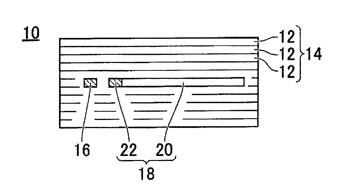
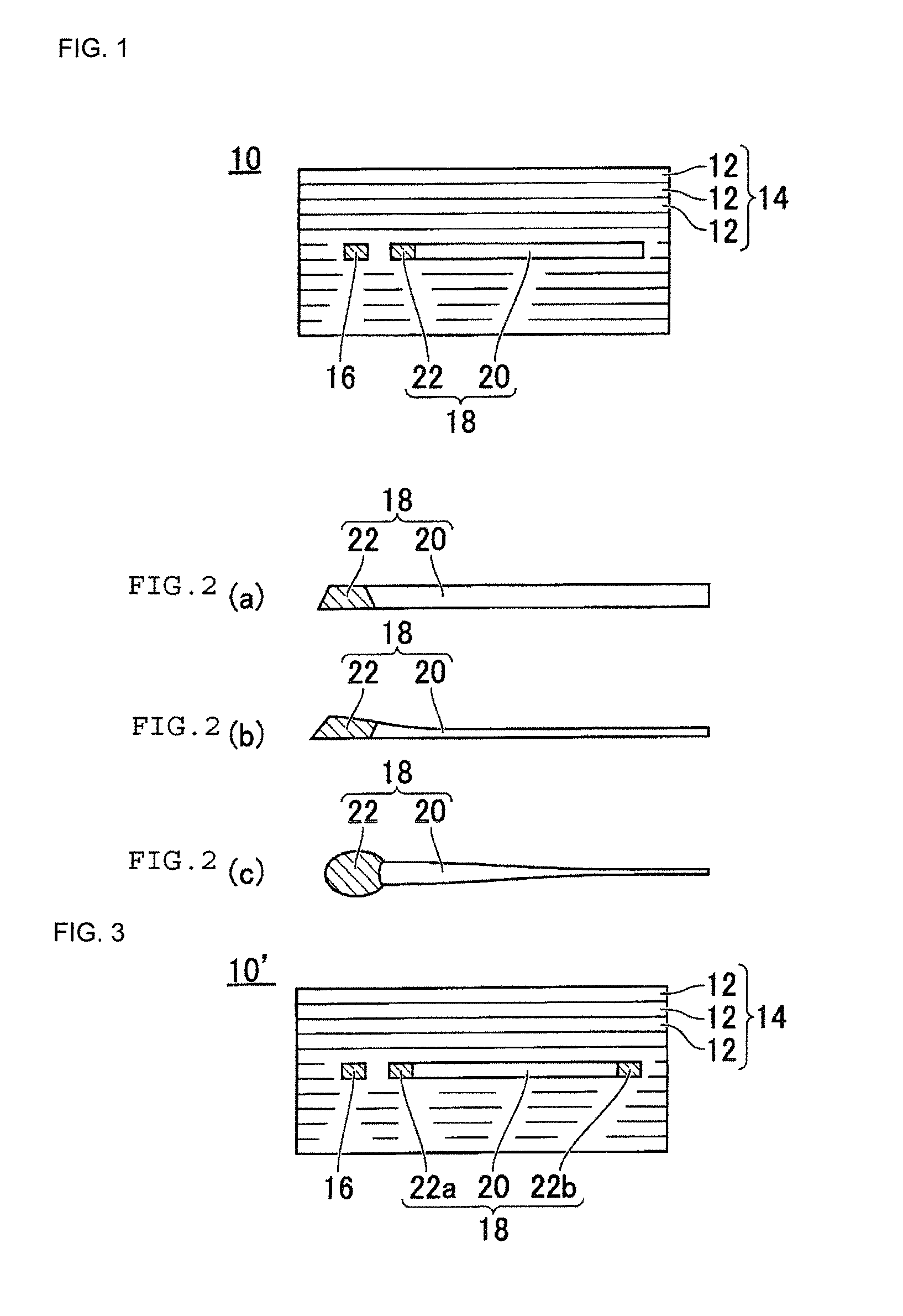
[0026]The electronic component 10 of the first embodiment functions as the electronic component 10 when there is only the multilayer ceramic substrate 14 and functions as an electronic component module when an electronic component element (not illustrated) is mounted on the multilayer ceramic substrate 14.

[0027]The material of the ceramic layers 12 is preferably one including barium oxide, silicon oxide or alumina as a main component. In addition, instead of that, a material obtained by for example adding a glass component, which acts as a sintering additive, to a material acting as a ceramic filler such as alumina or barium titanate may be used as the material of the ceramic layers 12. However, in the case where a reducing atmosphere is necessary in the firing conditions due to the material characteristics of for example an electrode material to be described later, a composition that is not reduced when fired in the reducing atmosphere needs to be selected.

[0028]In the electronic c...

second embodiment

[0042]Similarly to the electronic component 10, the electronic component 10′ of the second embodiment functions as the electronic component 10′ when there is only the multilayer ceramic substrate 14 and functions as an electronic component module when an electronic component element (not illustrated) is mounted on the multilayer ceramic substrate 14.

[0043]In the electronic component 10′ of the second embodiment, the wiring electrode 16 and the planar electrode 18 are both formed on the same ceramic layer 12. The wiring electrode 16 is linearly formed on the ceramic layer 12. The planar electrode 18 is planarly formed so as to be adjacent to and spaced apart from the wiring electrode 16 at a certain interval. An edge portion 22a is formed in a region of the planar electrode 18 that is adjacent to and spaced apart from the wiring electrode 16 at the certain interval. In addition, an edge portion 22b is formed in a region that is on the opposite side to the region of the planar electro...


PUM

PropertyMeasurementUnit
widthaaaaaaaaaa
widthaaaaaaaaaa
widthaaaaaaaaaa

Abstract

The electronic component of this invention includes a multilayer ceramic substrate 14 composed of a plurality of ceramic layers 12. A wiring electrode 16 and a planar electrode 18 are formed on a ceramic layer 12, which is an insulating layer. The planar electrode 18 is formed so as to be spaced apart from the wiring electrode 16 at the certain interval. An edge portion 22 is formed in a region of the planar electrode 18 adjacent to and spaced apart from the wiring electrode 16 at a certain interval. A central portion 20 is formed in a region of the planar electrode 18 other than the edge portion 22. At least the composition of the central portion 20 is different from the composition of the wiring electrode 16, and the composition of the edge portion 22 is the same as the composition of the wiring electrode 16.

Description

BACKGROUND OF THE INVENTION[0001]1. Field of the Invention[0002]The present invention relates to an electronic component including a ceramic substrate in which a wiring electrode and a planar electrode are formed on a surface of a ceramic layer, and to a manufacturing method therefor.[0003]2. Description of the Related Art[0004]It is disclosed that optimum impedance characteristics are achieved for both a general signal line and a differential signal line by efficiently arranging a power supply portion and a ground portion on a layer inside a multilayer ceramic substrate, which is an electronic component, described in Patent Document 1. One feature of this configuration is that a surface on which the differential signal line is arranged includes a first region in which the differential signal line is arranged and a second region in which either of a power supply plane and a ground plane is arranged. In other words, it is disclosed that the differential signal line, which is composed...

Claims


Application Information

Patent Timeline
Patent Type & Authority Applications(United States)
IPC IPC(8): H05K1/02H05K3/00H05K3/12H05K1/03
CPCH05K1/0298H05K1/0306H05K2201/0352H05K3/0067H05K3/12H05K1/0237H05K3/4629H01G4/30H01G4/012H01G4/12H05K1/025H05K1/092H05K1/162H05K2201/0209H05K2201/0212H05K2201/0391H05K2201/09336H05K2201/09736
Inventor NOMIYA, MASATO
Owner MURATA MFG CO LTD
Learn More