Laser nanomachining device and method

a laser nano-machining and nano-machining technology, applied in the direction of manufacturing tools, welding/soldering/cutting articles, electric/magnetic/electromagnetic heating, etc., can solve the problems of limited sample size, channel, and non-linear effects, and especially kerr effects

Active Publication Date: 2015-06-11
CENT NAT DE LA RECHERCHE SCI +1
View PDF5 Cites 87 Cited by
  • Summary
  • Abstract
  • Description
  • Claims
  • Application Information

AI Technical Summary

Benefits of technology

[0013]The Applicants have demonstrated that such a device makes high-aspect-ratio nano-drilling possible in any type of material having a spectral band of transparency to light waves, including semiconductors. Specifically, by virtue of a temporal shaping of the incident pulses, non-linear effects, and especially the Kerr effects responsible for nonuniformity in the formation of the plasma channel, are limited in the sample.
[0

Problems solved by technology

Specifically, by virtue of a temporal shaping of the incident pulses, non-linear effects, and especially the

Method used


Image

  • Laser nanomachining device and method
  • Laser nanomachining device and method
  • Laser nanomachining device and method

Examples


Embodiment Construction

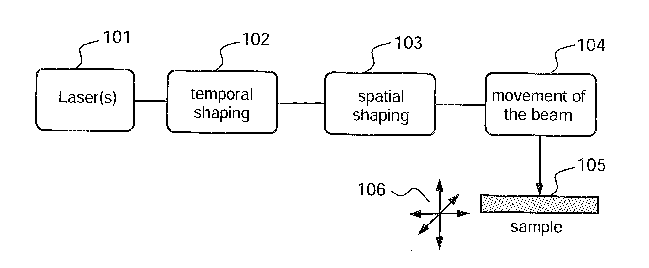
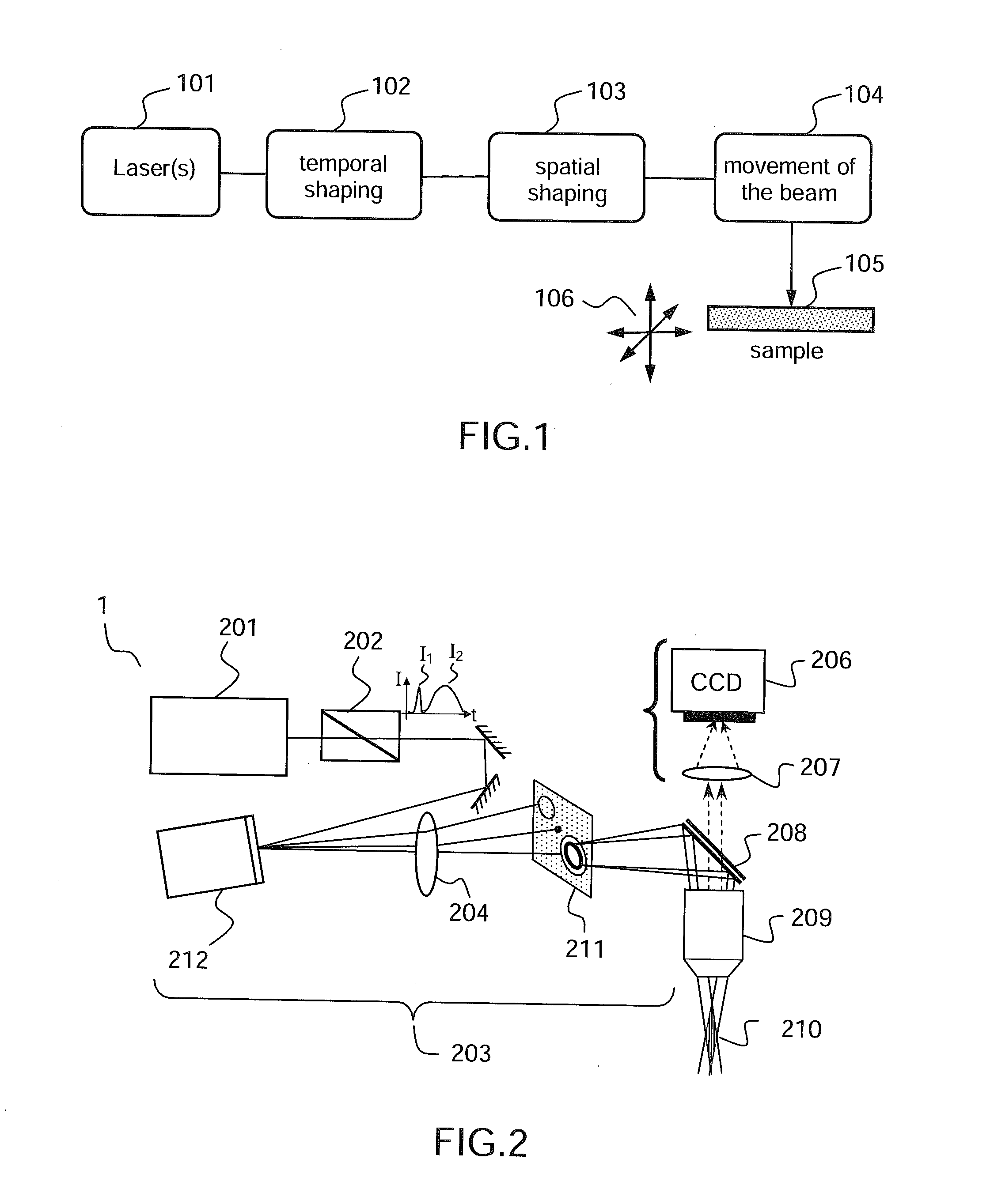
[0049]FIG. 1 shows a diagram illustrating the nanomachining method according to one embodiment of the invention.

[0050]In this example, the nanomachining method comprises the emission 101 of a beam by a pulsed laser source, and focusing of the beam on a sample 105 to be drilled, after a step of temporal shaping 102 and a step of spatial shaping 103, which will be described in greater detail below. Scanning 104 of the beam and translation / rotation (symbolized by the arrows 106) of the sample may allow the beam and the sample to be moved relative to each other in order to produce, sequentially, a plurality of drill holes in a given sample.

[0051]In this example, the temporal shaping 102 comprises generating, from a single laser source, a first and a second light pulse in a spectral band comprised in a transparency band of the material from which the sample is formed. The transparency band of the material is the spectral domain in which the absorption coefficient of the medium is lower t...


PUM

PropertyMeasurementUnit
Timeaaaaaaaaaa
Timeaaaaaaaaaa
Lengthaaaaaaaaaa

Abstract

According to one aspect, the invention relates to a device (1, 2, 3) for laser nanomachining a sample made of a material having a given transparency band, the device comprising: a focusing module (203, 703) allowing a nondiffracting beam (210, 710) to be generated, along a focusing line generally oriented along the optical axis of the focusing module, from a given incident beam; first means (202, 702) for emitting a first light pulse (I1) of spectral band comprised in the transparency band of said material, able to generate in said material, after focusing by said focusing module, a plasma of free charges along said focusing line via multiphoton absorption, thus forming a “plasma channel”; and second means (202, 702) for emitting at least one second electromagnetic wave (I2) of spectral band comprised in the transparency band of said material, which wave(s) is/are intended to be spatially superposed on said plasma channel in order to heat said material via absorption by the free charges of the plasma.

Description

PRIOR ART[0001]1. Technical Field of the Invention[0002]The present invention relates to a laser nanomachining method and device, especially suitable for high-aspect-ratio nano-drilling or wafer bonding.[0003]2. Prior Art[0004]In the context for example of the drilling of channels or “vias” in or through semiconductor wafers for micro- and nano-electronics and photovoltaics, it is sought to obtain deep drill holes, i.e. drill holes having a high aspect ratio, aspect ratio being defined by the ratio of the length of the hole drilled to its diameter. However, independently of the technique used, it is extremely difficult to reach deep hole drilling. Specifically, it is difficult to extract material from and deliver energy to a hole whose diameter is much smaller than its depth. These drilling techniques for example comprise focused ion beam techniques (so-called “e-beam” methods) or photolithography followed by chemical etching (or RIE for “reactive ion etching”). E-beam technology re...

Claims


Application Information

Patent Timeline
IPC IPC(8): B23K26/06H01L21/324B23K26/40H01L21/67H05K3/00B23K26/38
CPCB23K26/0635H05K3/0038B23K26/381H01L21/3247B23K26/0613H01L21/67115B23K26/4075B23K26/382B23K26/40B23K26/55B23K2101/40B23K2103/50B23K2103/52B23K26/0624B23K2103/40
Inventor COURVOISIER, FRANCOISLACOURT, PIERRE-AMBROISEJACQUOT, MAXIMEFURFARO, LUCADUDLEY, JOHNDE LABACHELERIE, MICHEL
Owner CENT NAT DE LA RECHERCHE SCI
Why Eureka
Try Eureka