Advanced crucible support and thermal distribution management

a technology of crucible support and thermal distribution management, which is applied in the direction of polycrystalline material growth, crystal growth process, aluminium compound, etc., can solve the problems of any automation requirements for the crucible loading process, the temperature gradient at the base of the crucible is not ideal, and the crucible cannot meet the requirements of loading process automation, so as to prevent excessive heat from reaching the heat exchanger, improve the heat flow, and increase the heat flow

Active Publication Date: 2015-06-25
GTAT CORPORATION
View PDF7 Cites 10 Cited by
  • Summary
  • Abstract
  • Description
  • Claims
  • Application Information

AI Technical Summary

Benefits of technology

[0008]According to the disclosed embodiments, an advanced crucible support system is described that allows for greater heat flow to and from the bottom of a crucible, while also preventing excessive heat from reaching a heat exchanger. In particular, a support base is described that includes one or more vents enabling improved heat flow throughout the system.

Problems solved by technology

The current crucible support design, however, limits the “view factor” for radiated heat generated from a furnace's heating element from reaching the bottom of the crucible.
Because of this fact, the temperature gradient at the base of the crucible is not ideal.
Additionally, the current method of using the crucible itself as a means for establishing a physical interface for a given crucible manipulating device is presenting challenges and safety concerns as the physical size and mass of crucible and charge size increases.
The ring is currently manually loaded into the furnace as its own discrete loading step, and then several steps follow before a crucible is fully charged and considered ready for the crystal growth process, thus causing issues for any automation requirements for the crucible loading process.

Method used


Image

  • Advanced crucible support and thermal distribution management
  • Advanced crucible support and thermal distribution management
  • Advanced crucible support and thermal distribution management

Examples


Embodiment Construction

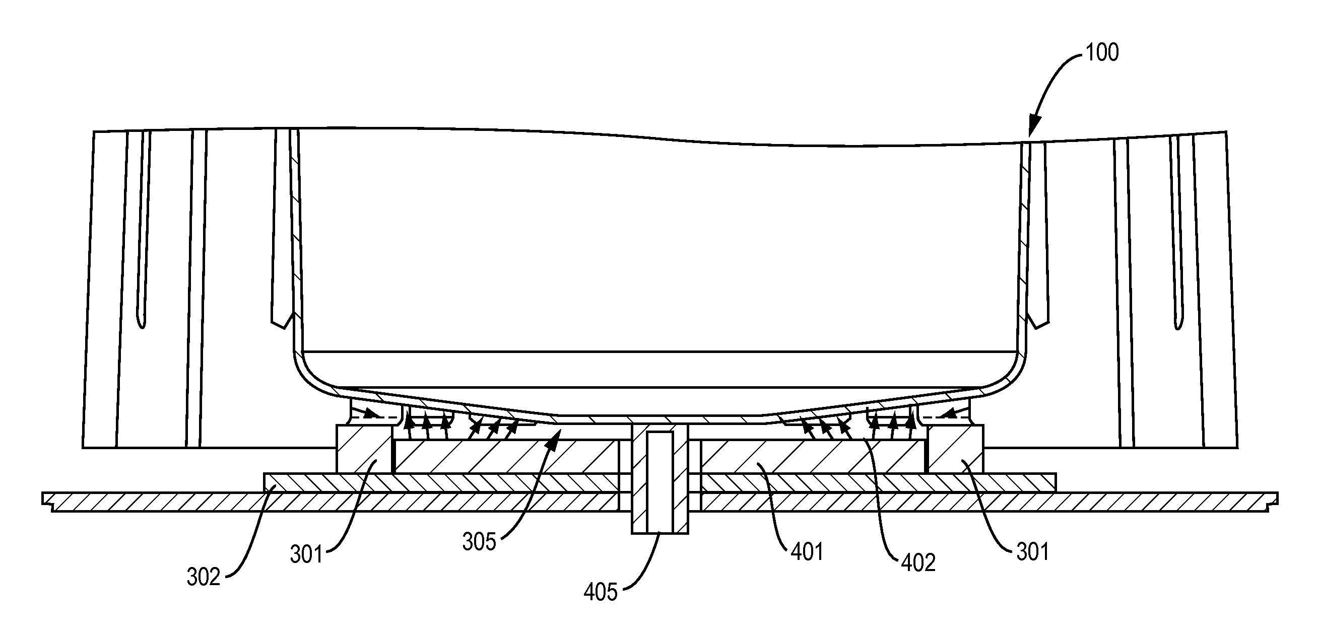
[0026]The present invention relates to a crucible support system for a crystal growth apparatus.

[0027]The terminology used herein is for the purpose of describing particular embodiments only and is not intended to be limiting of the disclosure. As used herein, the singular forms “a”, “an” and “the” are intended to include the plural forms as well, unless the context clearly indicates otherwise. It will be further understood that the terms “comprises” and / or “comprising,” when used in this specification, specify the presence of stated features, integers, steps, operations, elements, and / or components, but do not preclude the presence or addition of one or more other features, integers, steps, operations, elements, components, and / or groups thereof. As used herein, the term “and / or” includes any and all combinations of one or more of the associated listed items.

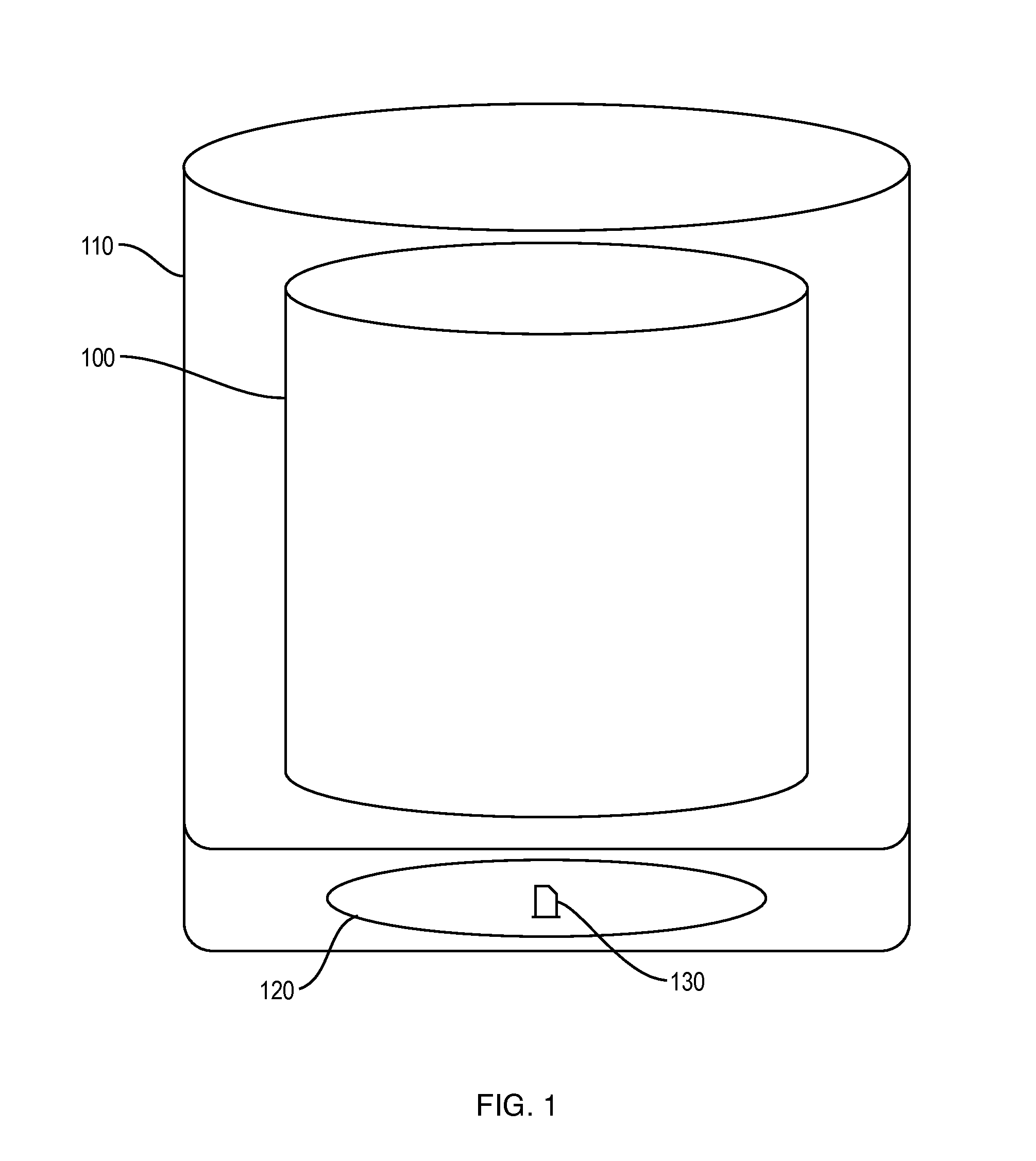
[0028]FIG. 1 illustrates a conventional crystalline material growth system. As shown in FIG. 1, a conventional crystalline ma...


PUM

PropertyMeasurementUnit
temperaturesaaaaaaaaaa
angleaaaaaaaaaa
angleaaaaaaaaaa

Abstract

According to the disclosed embodiments, an advanced crucible support system is described that allows for greater heat flow to and from the bottom of a crucible, preferably while also preventing excessive heat from reaching a heat exchanger. In particular, a support base is described that includes one or more vents enabling improved heat flow throughout the system. Also, according to one or more additional embodiments, the functionality of the crucible support is adapted to be leveraged by a crucible manipulating device. For example, the support plate may have a plurality of slots for insertion of a “lifting arm”, such that the entire support plate assembly, as well as the crucible itself while on the support assembly, may be lifted and transported as a single unit.

Description

CROSS-REFERENCE TO RELATED APPLICATIONS[0001]The present application is a continuation-in-part of corresponding U.S. patent application Ser. No. 14 / 488,501 filed Sep. 17, 2014, which claims the benefit of U.S. Patent Application No. 61 / 884,503 filed Sep. 30, 2013, both of which are incorporated herein by reference.BACKGROUND OF THE INVENTION[0002]1. Field of the Invention[0003]The present disclosure relates generally to crystalline material growth systems, and, more particularly, to an advanced crucible support and thermal distribution management.[0004]2. Description of the Related Art[0005]Crystal growth apparatuses or furnaces, such as directional solidification systems (DSS) and heat exchanger method (HEM) furnaces, involve the melting and controlled resolidification of a feedstock material, such as alumina or silicon, in a crucible to produce an ingot or boule. Production of a solidified product from molten feedstock occurs in several identifiable steps over many hours. For exam...

Claims


Application Information

Patent Timeline
Patent Type & Authority Applications(United States)
IPC IPC(8): C30B11/00C30B29/20
CPCC30B11/002C30B29/20C30B11/003C30B15/14C30B35/00Y10T117/1068Y10T117/1092
Inventor BROYER, DAVID F.ZHANG, HUIDUANMU, NINGWITTING, IAN T.
Owner GTAT CORPORATION
Why Eureka
Try Eureka