

Organic electroluminescence element and material for organic electroluminescence element
a technology of electroluminescent elements and materials, applied in the direction of luminescent compositions, thermoelectric devices, organic chemistry, etc., can solve the problems of insufficient luminous efficiency, inability to achieve high-efficiency light emission, and material use not satisfactory, so as to improve electron transporting properties, electron transporting properties, and hole transporting properties
- Summary
- Abstract
- Description
- Claims
- Application Information
AI Technical Summary
Benefits of technology
Problems solved by technology
Method used
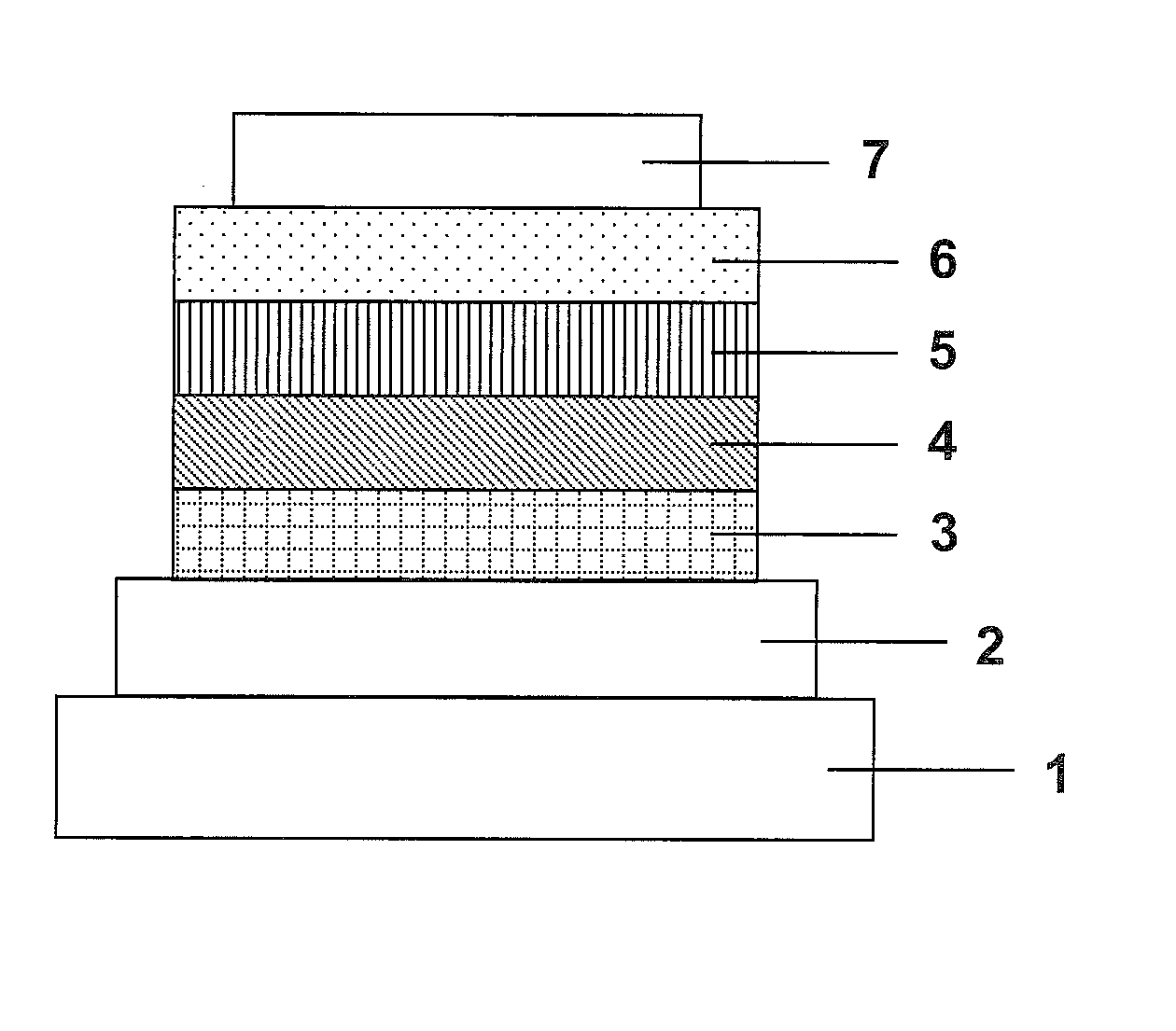
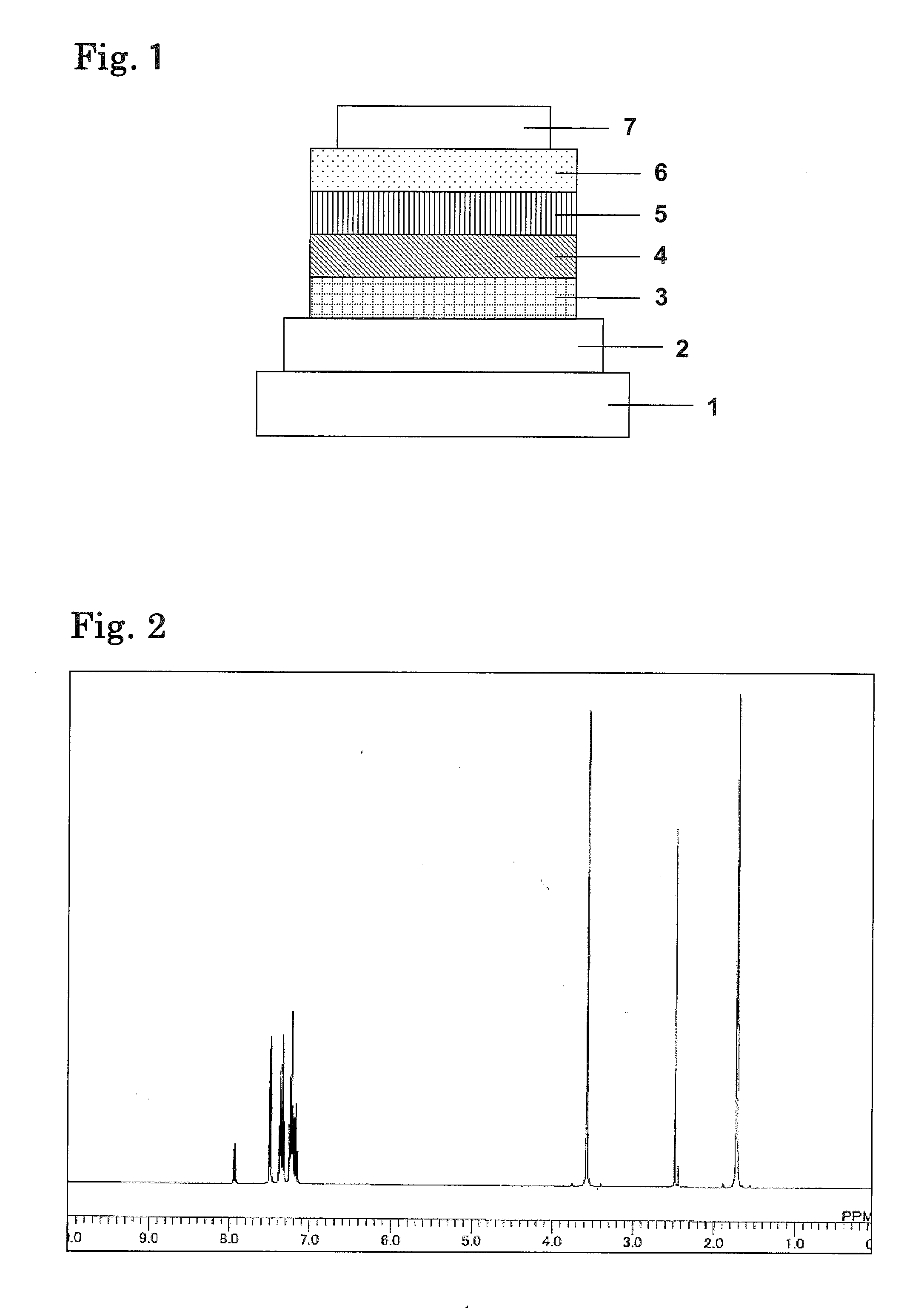
Image

Examples
example 1
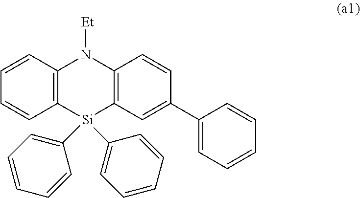
Synthesis of Compound (1-25)
[0109]
[0110]Under a nitrogen atmosphere, 34.4 g (0.20 mol) of 1-amino-2-bromobenzene, 67.9 g (0.24 mol) of 1-bromo-2-iodobenzene, 9.16 g (0.01 mol) of tris(dibenzylideneacetone)dipalladium(0), 11.1 g (0.02 mol) of 1,1′-bis(diphenylphosphino)ferrocene, and 400 ml of toluene were loaded and the mixture was stirred at 120° C. for 3 hr. Subsequently, the reaction solution was cooled to room temperature, an inorganic salt was separated by filtration, and then the solvent was removed by evaporation under reduced pressure. The resultant residue was purified by column chromatography to provide 55.8 g (0.17 mol, 85% yield) of an intermediate (A-1).
[0111]Under a nitrogen atmosphere, 7.4 g (0.17 mol) of sodium hydride having a purity of 56.4%, and 150 ml of DMF were loaded and the mixture was stirred at room temperature. 47.5 g (0.15 mol) of the intermediate (A-1) dissolved in 200 ml of DMF were added dropwise thereto, and the mixture was stirred for 1 hr. 25.0 g (0...
example 2
Synthesis of Compound (1-1)
[0117]
[0118]Under a nitrogen atmosphere, 0.05 g (0.00023 mol) of palladium acetate and 8 ml of xylene were loaded and the mixture was stirred at room temperature. 0.19 g (0.00092 mol) of t-butylphosphine was added thereto and the mixture was stirred at 80° C. for 1 hr. Separately, under a nitrogen atmosphere, 8.0 g (0.023 mol) of the intermediate (A-4), 1.51 g (0.011 mol) of 2,6-dibromopyridine, 4.4 g (0.046 mol) of sodium-t-butoxide, and 80 ml of xylene were loaded and the mixture was stirred at 80° C. The previously prepared solution was added thereto, and the mixture was stirred at 145° C. for 2 hr. Subsequently, the reaction solution was cooled to room temperature, an inorganic salt was separated by filtration, and then the solvent was removed by evaporation under reduced pressure. The resultant residue was purified by column chromatography to provide 7.6 g (0.01 mol, 89% yield) of a compound (1-1).
[0119]APCI-TOFMS, m / z 774 [M+H]+
example 3
Synthesis of Compound (3-2)
[0120]
[0121]Under a nitrogen atmosphere, 0.08 g (0.00036 mol) of palladium acetate and 10 ml of xylene were loaded and the mixture was stirred at room temperature. 0.29 g (0.0014 mol) of t-butylphosphine was added thereto and the mixture was stirred at 80° C. for 1 hr. Separately, under a nitrogen atmosphere, 12.6 g (0.036 mol) of the intermediate (A-4), 7.11 g (0.017 mol) of 2,8-diiododibenzofuran, 6.92 g (0.072 mol) of sodium-t-butoxide, and 100 ml of xylene were loaded and the mixture was stirred at 80° C. The previously prepared solution was added thereto, and the mixture was stirred at 145° C. for 2 hr. Subsequently, the reaction solution was cooled to room temperature, an inorganic salt was separated by filtration, and then the solvent was removed by evaporation under reduced pressure. The resultant residue was purified by column chromatography to provide 9.8 g (0.011 mol, 67% yield) of a compound (3-2).
[0122]APCI-TOFMS, m / z 863 [M+H]+
PUM
| Property | Measurement | Unit |
|---|---|---|
| work function | aaaaa | aaaaa |
| transmittance | aaaaa | aaaaa |
| sheet resistance | aaaaa | aaaaa |
Abstract
Description
Claims
Application Information