Surface treatment method and coating agent
a surface treatment method and coating agent technology, applied in the direction of liquid/solution decomposition chemical coating, mechanical vibration separation, foundation moulding apparatus, etc., can solve the problems of increasing film thickness, carbon film reinforced by using the technology disclosed, and mold side of carbon film may not be sufficiently densified, so as to reduce the occurrence of initial peeling and improve the fluidity of molten aluminum
- Summary
- Abstract
- Description
- Claims
- Application Information
AI Technical Summary
Benefits of technology
Problems solved by technology
Method used
Image
Examples
first embodiment
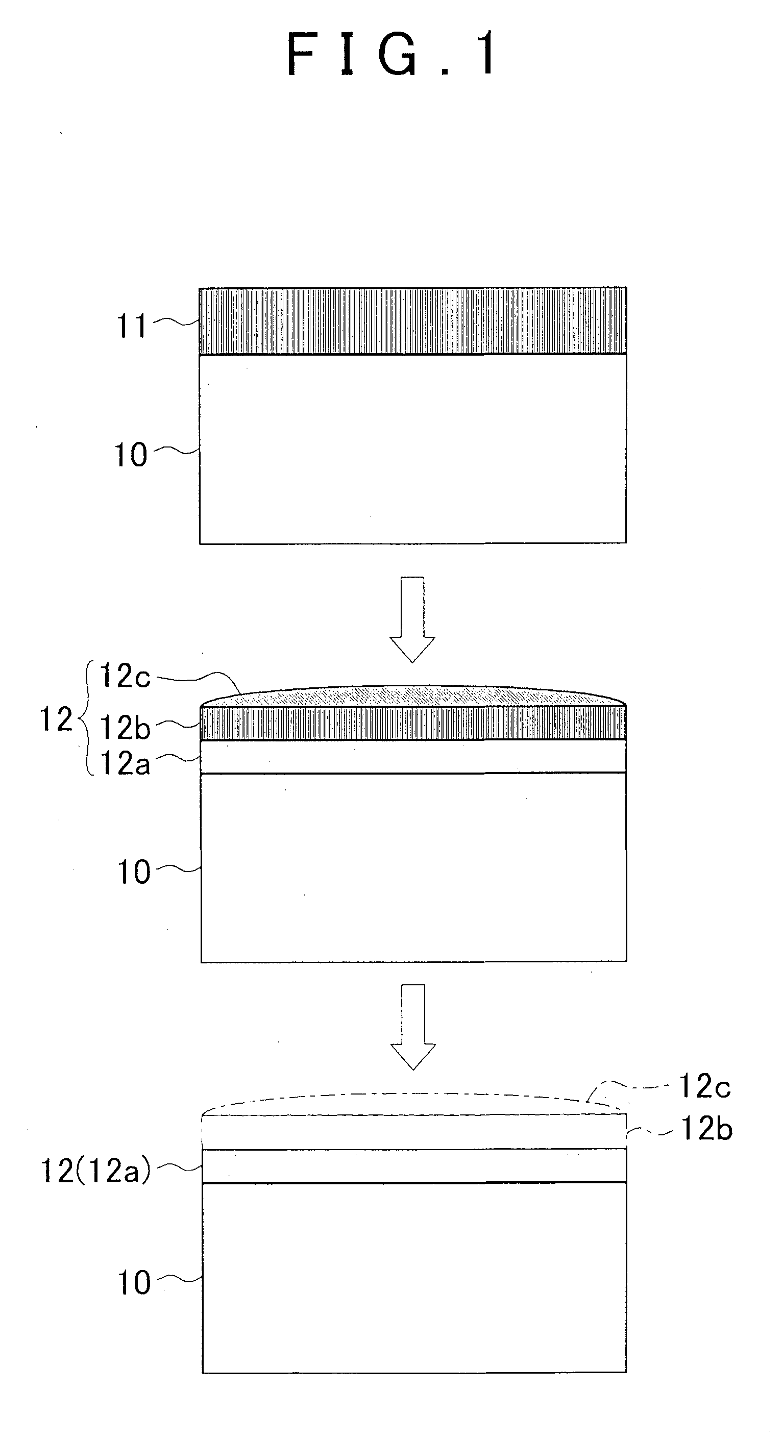
[0044]Below, a surface treatment method of a first embodiment will be described.
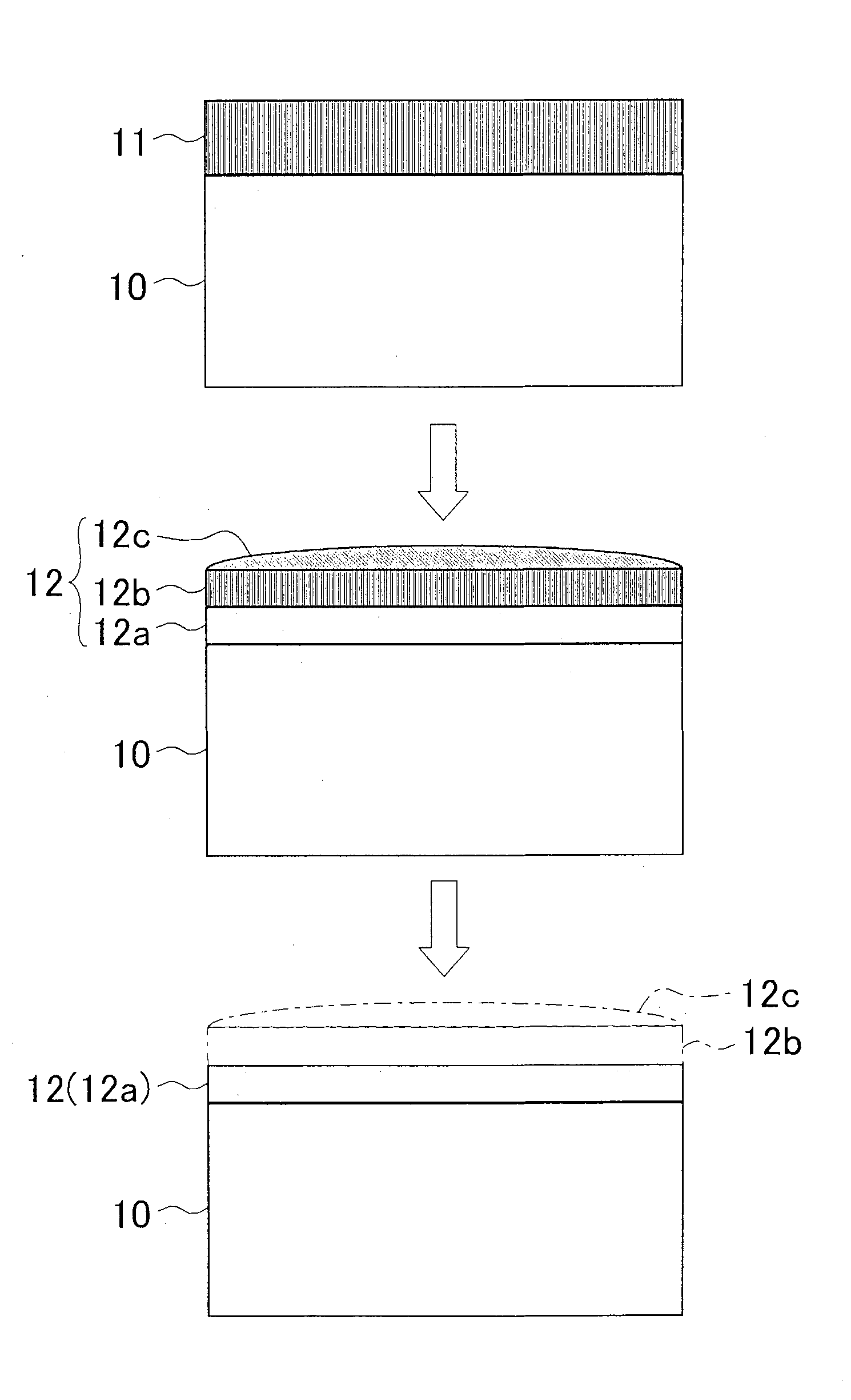
[0045]As shown in FIG. 1, the first embodiment is a surface treatment method on a base material coated a surface with a carbon film.
[0046]First, a base material 10 will be described.
[0047]The base material 10 is a mold for casting formed in a substantially rectangular parallelepiped, and is formed of iron. The base material 10 is coated with a carbon film 11 on the surface (the top surface of the base material 10 in FIG. 1). The base material 10 is, for example, placed in a furnace under an inert gas (such as a nitrogen gas) atmosphere, and is heated to a prescribed temperature. At that step, an active gas (such as an acetylene gas) is supplied into the furnace, so that the surface of the base material 10 is coated with the carbon film 11.
[0048]In the first embodiment, the carbon film 11 is a carbon nanofiber.
[0049]Then, a description will be given to the procedure of the surface treatment method of the ...
second embodiment
[0088]Then, a description will be given to a surface treatment method of a
[0089]As shown in FIG. 3, the second embodiment is a surface treatment method on a base material which is surface coated with a nitrogen film, and on which the nitrogen film is coated with a carbon film.
[0090]A base material 20 is a mold for casting formed in a substantially rectangular parallelepiped, and is formed of iron. The base material 20 is coated on the surface thereof (the top surface of the base material 20 in FIG. 3) with a nitrogen film 21, and the nitrogen film 21 is coated with a carbon film 22. In other words, the nitrogen film 21 is situated between the base material 20 and the carbon film 22. The nitrogen film 21 and the carbon film 22 form a coating portion.
[0091]In the second embodiment, the carbon film 22 is a carbon nanofiber.
[0092]Then, a description will be given to the procedure of a surface treatment method of the second embodiment.
[0093]First, with the surface treatment method of the...
third embodiment
[0116]Then, a description will be given to a surface treatment method of a
[0117]As shown in FIG. 4, the third embodiment is a surface treatment method on a base material which is coated with a nitrogen film on the topmost surface side of a coating portion.
[0118]A base material 30 of the third embodiment is a mold for casting formed in a substantially rectangular parallelepiped, and is formed of iron. The base material 30 is coated on the surface thereof (the surface of the base material 30 in FIG. 4) with a carbon film 31, and the carbon film 31 is coated with a nitrogen film 32. In other words, the nitrogen film 32 is situated at the topmost surface side among the base material 30, the carbon film 31, and the nitrogen film 32. Namely, the base material 30 is coated with the nitrogen film 32 on the topmost surface side of the coating portion (the topmost side in FIG. 4).
[0119]Incidentally, the base material may be desirably coated on the topmost surface side of the coating portion w...
PUM
| Property | Measurement | Unit |
|---|---|---|
| temperature | aaaaa | aaaaa |
| temperatures | aaaaa | aaaaa |
| temperatures | aaaaa | aaaaa |
Abstract
Description
Claims
Application Information
 - R&D
- Intellectual Property
- Life Sciences
- Materials
- Tech Scout
- Unparalleled Data Quality
- Higher Quality Content
- 60% Fewer Hallucinations
Browse by: Latest US Patents, China's latest patents, Technical Efficacy Thesaurus, Application Domain, Technology Topic, Popular Technical Reports.
© 2025 PatSnap. All rights reserved.Legal|Privacy policy|Modern Slavery Act Transparency Statement|Sitemap|About US| Contact US: help@patsnap.com


