

Conductive shaft and conductive roll for oa equipment using the shaft, and method of producing conductive shaft
- Summary
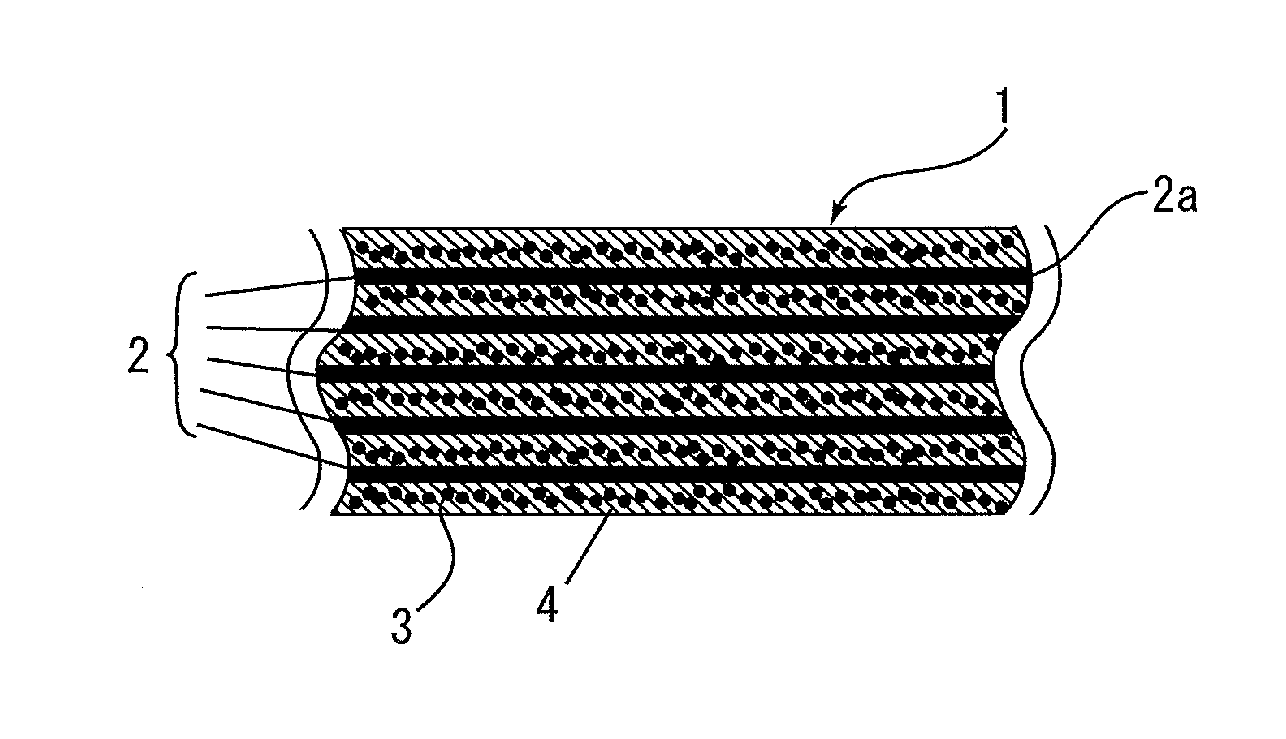
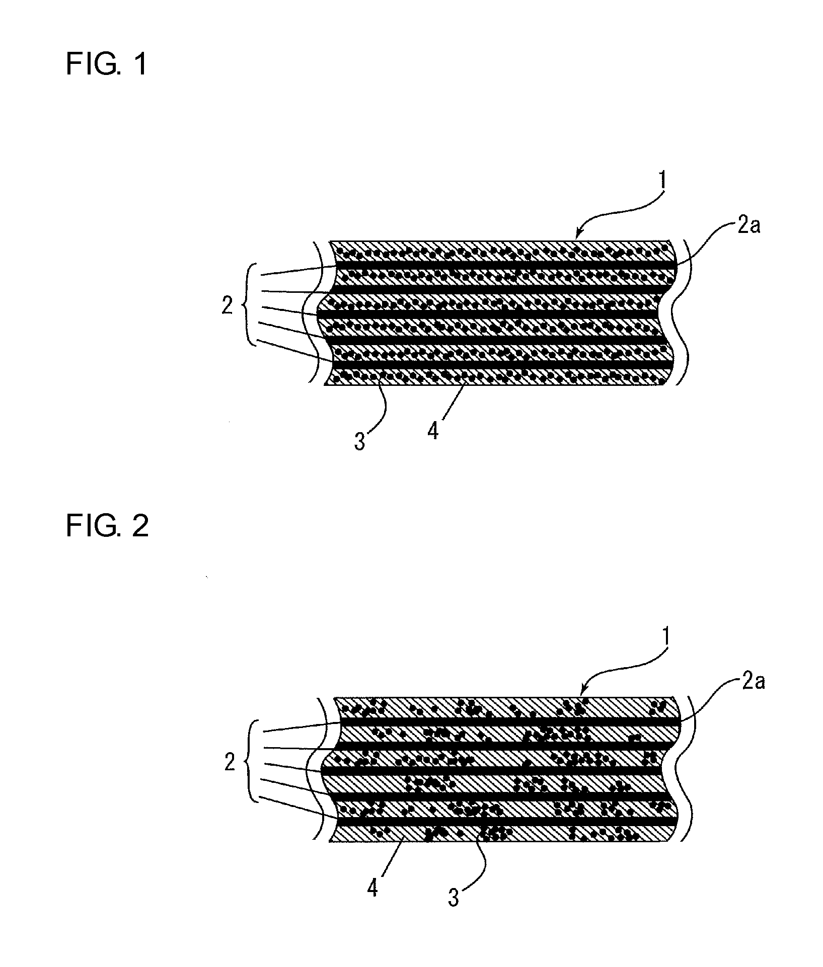
- Abstract
- Description
- Claims
- Application Information
AI Technical Summary
Benefits of technology
Problems solved by technology
Method used
Image

Examples
examples
[0047]Next, Examples are described together with Comparative Examples. However, the present invention is not limited to these examples, and other examples are permitted as long as the other examples do not deviate from the gist of the present invention.
[0048]First, the following materials were prepared prior to Examples and Comparative Examples.
[0049][Thermosetting Resin (A1)]
Unsaturated polyester resin (U-PICA 3140 manufactured by Japan U-Pica Company Ltd.)
[0050][Carbon Black (B1)]
DENKA BLACK (average particle diameter: 35 nm, DBP oil absorption: 160 ml / 100 g) manufactured by Denki Kagaku Kogyo Kabushiki Kaisha
[0051][Carbon Black (B2)]
SEAST TA (average particle diameter: 122 nm, DBP oil absorption: 42 ml / 100 g) manufactured by Tokai Carbon Co., Ltd.
[0052][Dispersant (C1)]
Alkylammonium salt (BYK-9076 manufactured by BYK)
[0053][Dispersant (C2)]
Copper phthalocyaninesulfonic acid ammonium salt (SOLSPERSE 5000 manufactured by Lubrizol Japan Limited)
[0054][Dispersant (C3)]
SOLSPERSE 88000...
example 10
[0070]A conductive coating layer was formed on the entirety of the surface of a shaft produced in the same manner as in Example 1 by the following coating treatment 1.
[Coating Treatment 1]
[0071]First, the shaft was subjected to an etching treatment with a 200 g / L aqueous solution of NaOH at a temperature of 40° C. for 10 minutes. Next, the shaft was immersed in a Pd catalyst-providing agent (OPC-50 INDUCER manufactured by Okuno Chemical Industries Co., Ltd.) at 40° C. for 5 minutes. Thus, its surface was provided with a Pd catalyst. Subsequently, the shaft was immersed in an activator (OPC-150 CRYSTER manufactured by Okuno Chemical Industries Co., Ltd.) at 25° C. for 5 minutes. Thus, a Pd ion was metallized (activation treatment). After the entirety of the surface of the shaft had been subjected to a pre-plating treatment as described above, the shaft was immersed in an electroless nickel plating liquid (TMP CHEMICAL NICKEL HRT manufactured by Okuno Chemical Industries Co., Ltd.) at...
example 11
[0072]A conductive coating layer was formed on the entirety of the surface of a shaft produced in the same manner as in Example 4 by the coating treatment 1.
PUM
| Property | Measurement | Unit |
|---|---|---|
| Fraction | aaaaa | aaaaa |
| Percent by mass | aaaaa | aaaaa |
| Percent by mass | aaaaa | aaaaa |
Abstract
Description
Claims
Application Information