
Diamond-like carbon coating on chain guides and tensioning arms for internal combustion engines

a technology of carbon coating and chain guide, which is applied in the direction of superimposed coating process, mechanical equipment, gearing, etc., can solve the problems of generating undesirable engine noise, affecting the performance of the engine, and the plastic version of the component still suffers from poor wear characteristics, so as to avoid the risk of substrate deformation, high surface properties, and low friction

Inactive Publication Date: 2015-09-17
FORD GLOBAL TECH LLC
View PDF8 Cites 3 Cited by
  • Summary
  • Abstract
  • Description
  • Claims
  • Application Information

AI Technical Summary

Benefits of technology

This patent describes a process to apply a durable and abrasion-resistant coating of diamond-like carbon to the surfaces of plastic components. This coating is formed using a low-temperature process that avoids deformation of the substrate. The coated components have highly desirable properties such as low friction and compatibility with lubricants. This process is achieved through a hybrid of plasma-based ion implantation and deposition. The technical effects of this patent are improved wear resistance and surface properties on plastic components, which can enhance their performance and durability.

Problems solved by technology

While proving generally satisfactory, because of metal-on-metal friction today's metal chain tensioning arms and guides are sometimes known to wear prematurely and to generate an undesirable level of engine noise.
However, while solving the problem of engine noise caused by known metal tensioners and guides, the plastic versions of these components still suffer from poor wear characteristics.

Method used


Image

  • Diamond-like carbon coating on chain guides and tensioning arms for internal combustion engines
  • Diamond-like carbon coating on chain guides and tensioning arms for internal combustion engines
  • Diamond-like carbon coating on chain guides and tensioning arms for internal combustion engines

Examples


Embodiment Construction

[0018]In the following figures, the same reference numerals will be used to refer to the same components. In the following description, various operating parameters and components are described for different constructed embodiments. These specific parameters and components are included as examples and are not meant to be limiting.

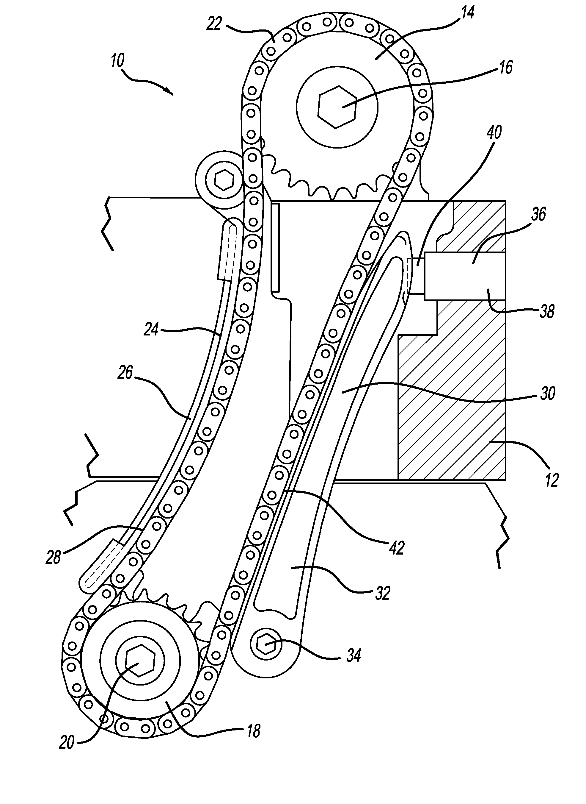
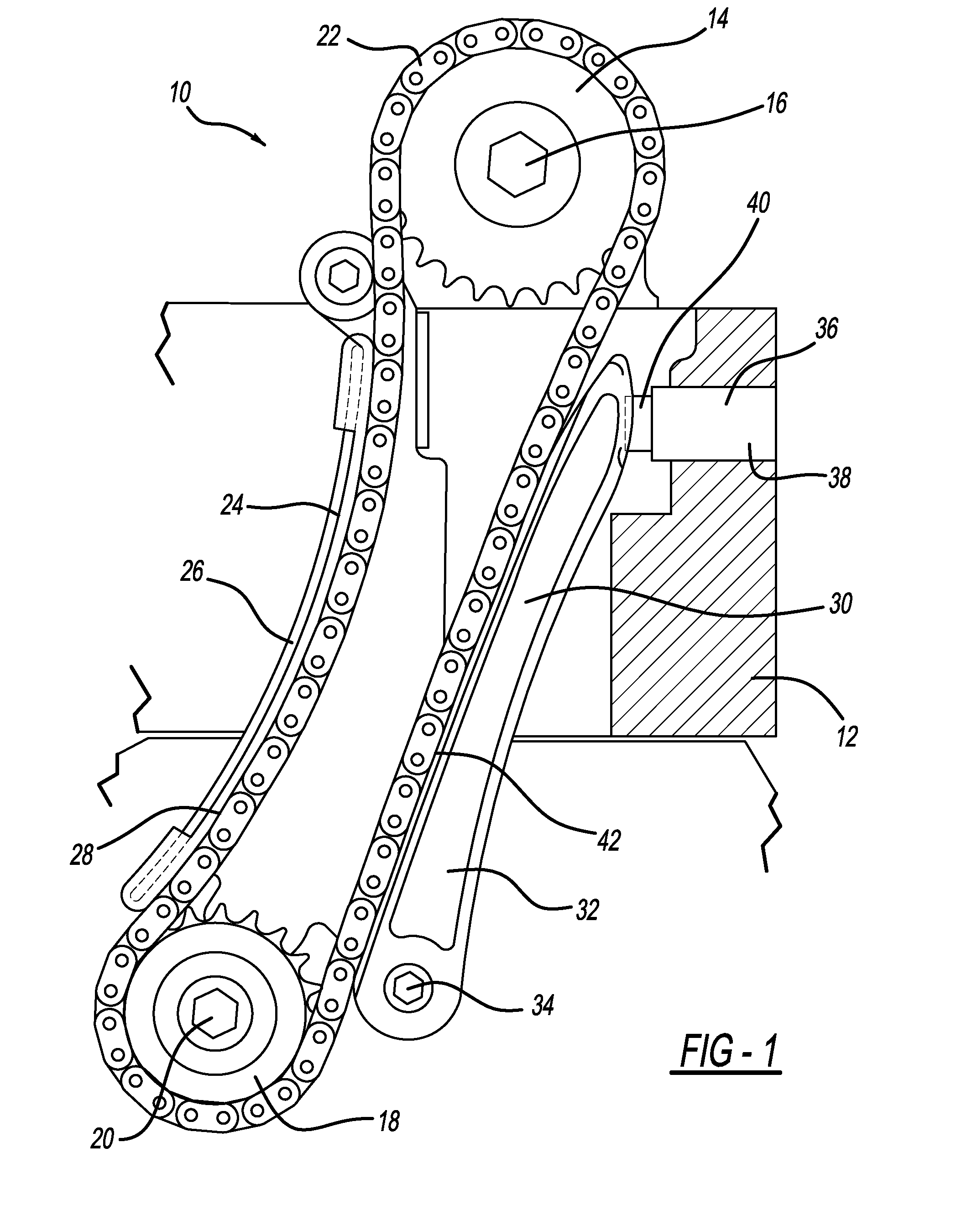
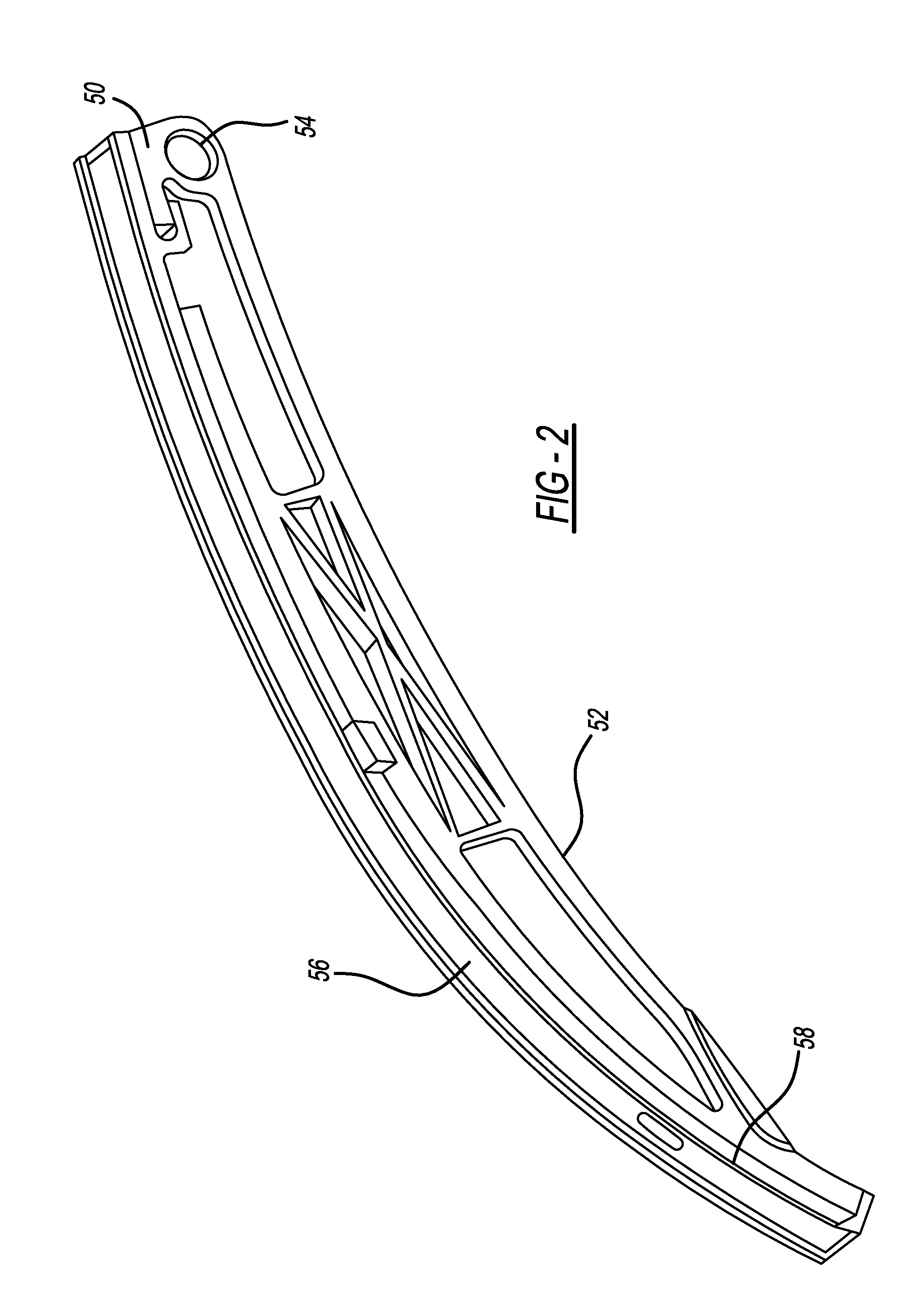
[0019]In general, the disclosed inventive concept provides a chain tensioning arm and a chain guide having a diamond like surface coating. FIG. 1 illustrates a schematic partial section of an internal combustion engine, generally illustrated as 10. The engine 10 is intended as being illustrative and not limiting and it is thus to be understood that the disclosed inventive concept can have a wide variety of applications to virtually any chain drive system having either or both a chain tensioning arm and a chain guide.

[0020]As shown in FIG. 1, the engine 10 includes an engine block 12, of which only a portion is illustrated. The engine 10 further includes a c...


PUM

PropertyMeasurementUnit
pulse voltageaaaaaaaaaa
temperatureaaaaaaaaaa

Abstract

A nylon chain tensioning arm and nylon chain guide having diamond-like carbon coatings are provided. The diamond-like carbon coating is formed on the substrate by methods including physical vapor deposition, for example, by sputtering or chemical vapor deposition of coating systems composed of various combinations of amorphous carbon. A preferred method for applying the diamond-like carbon coating to the nylon substrate is a hybrid process of plasma-based ion implantation and deposition. The chain tensioning arm or guide may be formed from any number of plastics appropriate to the purpose, although a synthetic polymer, such as the aliphatic polyamide nylon, is the preferred material. The substrate may be a conventional nylon or may be a composite reinforced with glass or carbon fibers. The diamond-like carbon coating may be applied to the nylon substrate by vapor deposition, either directly to the chain-contacting surface or upon a primed surface formed on the substrate prior to deposition.

Description

TECHNICAL FIELD[0001]The disclosed inventive concept relates generally to chain guides and tensioning arms used in conjunction with timing chains in internal combustion engines. More particularly, the disclosed inventive concept relates to chain guides and tensioning arms having wear-resistant, diamond-like carbon coatings.BACKGROUND OF THE INVENTION[0002]The modern internal combustion engine incorporates chain guides and chain tensioners in relation to valvetrain or balanceshaft chain drive systems. Such chains replace, for example, gears and timing belts that connect the crankshaft with the camshafts. While providing superior performance and durability when compared with earlier approaches to linking the crankshaft and the camshafts, timing chains must operate under a predetermined amount of tension to minimize wear and to reduce both vibration and noise.[0003]To answer this need, a timing chain is placed under tension over its entire travel by one or more chain tensioners. Chain ...

Claims


Application Information

Patent Timeline
Patent Type & Authority Applications(United States)
IPC IPC(8): F16H7/08C23C16/27C23C16/50C23C28/04C23C14/48C23C14/02C23C16/02F16H7/18C23C14/20
CPCF16H7/08F16H7/18C23C16/27C23C16/50F16H2007/185C23C14/48C23C14/022C23C16/0245C23C28/046C23C14/20
Inventor CHOTTINER, JEFFREY ELIOTWILLIAMS, RICK L.
Owner FORD GLOBAL TECH LLC
Learn More