X-ray method for the measurement, characterization, and analysis of periodic structures

a periodic structure and x-ray technology, applied in the field of interferometric measurement, characterization and analysis systems for observing period structures, can solve the problems of difficult unambiguous detection of tumors or anomalous tissue, difficult x-ray power, and simple absorption contrast imaging, and achieve high thermal conductivity, high x-ray brightness, and large x-ray power.

Active Publication Date: 2015-09-17
SIGRAY INC
View PDF3 Cites 64 Cited by
  • Summary
  • Abstract
  • Description
  • Claims
  • Application Information

AI Technical Summary

Benefits of technology

[0035]A particular advantage of the invention is that high x-ray brightness and large x-ray power may be achieved by using an x-ray target in which the microstructures of a high Z material are in close thermal contact with, or embedded in, a substrate of low Z material and high thermal conductivity, such as beryllium or diamond. The ability of the substrate to draw heat away from the x-ray generating material allows higher electron density and power to be used, generating greater x-ray brightness and power from each of the sub-sources. This results in the creation of individual, well-separated spatially coherent x-ray sub-sources from the high Z material, while the use of a substrate with low Z and low mass density minimizes the production of x-rays from the substrate that can lead to a reduction in image contrast.
is that high x-ray brightness and large x-ray power may be achieved by using an x-ray target in which the microstructures of a high Z material are in close thermal contact with, or embedded in, a substrate of low Z material and high thermal conductivity, such as beryllium or diamond. The ability of the substrate to draw heat away from the x-ray generating material allows higher electron density and power to be used, generating greater x-ray brightness and power from each of the sub-sources. This results in the creation of individual, well-separated spatially coherent x-ray sub-sources from the high Z material, while the use of a substrate with low Z and low mass density minimizes the production of x-rays from the substrate that can lead to a reduction in image contrast.

Problems solved by technology

Although x-ray shadowgraphs have become a standard medical diagnostic tool, there are problems with simple absorption contrast imaging.
Notably, for tests such as mammograms, variations in biological tissue may result in only a subtle x-ray absorption image contrast, making unambiguous detection of tumors or anomalous tissue difficult.
However, for the prior art configurations described so far, x-ray power is a problem.
However, electron bombardment of the target also causes heating, and the x-ray power that can be achieved is limited by the maximum total electron power that can fall on the microspot without melting the x-ray generating material.
A limited electron power means a limited x-ray power, and the low x-ray flux achievable with typical x-ray targets may lead to unacceptable long exposure times when used, for example, for mammography or other diagnostic tests involving live patients or animals.
The total x-ray flux can be increased by distributing higher electron power over a larger area, but then the source becomes less coherent, degrading the image contrast.
Coherent x-rays of higher brightness and sufficient flux can be achieved by using a synchrotron or free-electron laser x-ray source, but these machines may occupy facilities that cover acres of land, and are impractical for use in clinical environments.
Unfortunately, the current art of Talbot-Lau GBIs have many constraints for most practical applications such as semiconductor device inspection, including a requirement that both the source grating G0 and the analyzer grating G2 have fine pitches and apertures with large aspect ratios.
In this case, about 75% of the x-rays from the source are blocked due to area shadowing alone, and when gratings with large aspect ratios are used, greater losses occur due to angular shadowing.
As a result, both the G0 and G2 gratings must have small apertures and be of thickness sufficient to minimize unwanted x-ray transmission, which limits the efficient use of the x-rays from the source.
Furthermore, the loss from the analyzer grating G2 further results in a significantly higher dose (relative to the same system without a G2 grating) for the object under investigation to produce an image with good characteristics due to multiple exposures for phase-stepping and absorption of x-rays resulting in lower signal-to-noise.
When the object under investigation is a live animal or human, higher doses of ionizing radiation are undesirable and generally discouraged.
Smaller apertures can increase the possible image contrast and resolution by improving spatial coherence, but decreases the overall number of x-rays in the system, thus requiring longer exposure times. Moreover, with smaller apertures, these fine gratings become more difficult to manufacture.
Furthermore, building absorbing gratings such as G0 and G2 for these higher energy, shorter wavelength x-rays can present difficulties, as the thickness of the gratings must increase exponentially to maintain the same absorption factor for higher energy x-rays (the x-ray attenuation length is approximately proportional to Ekev3).
The preceding problems of Talbot-Lau GBIs using linear gratings, which can be used for collecting interference data in one dimension only, become more severe if one wishes to generate phase-contrast images in two orthogonal directions.
In addition to challenges associated with the imaging and registration processes, this approach may not be practical, especially when used with living subjects who may move or simply become impatient, and who will incur increased dosage (doubled) if the phase stepping must be performed in two directions.

Method used


Image

  • X-ray method for the measurement, characterization, and analysis of periodic structures
  • X-ray method for the measurement, characterization, and analysis of periodic structures
  • X-ray method for the measurement, characterization, and analysis of periodic structures

Examples


Embodiment Construction

Descriptions of Various Embodiments of the Invention

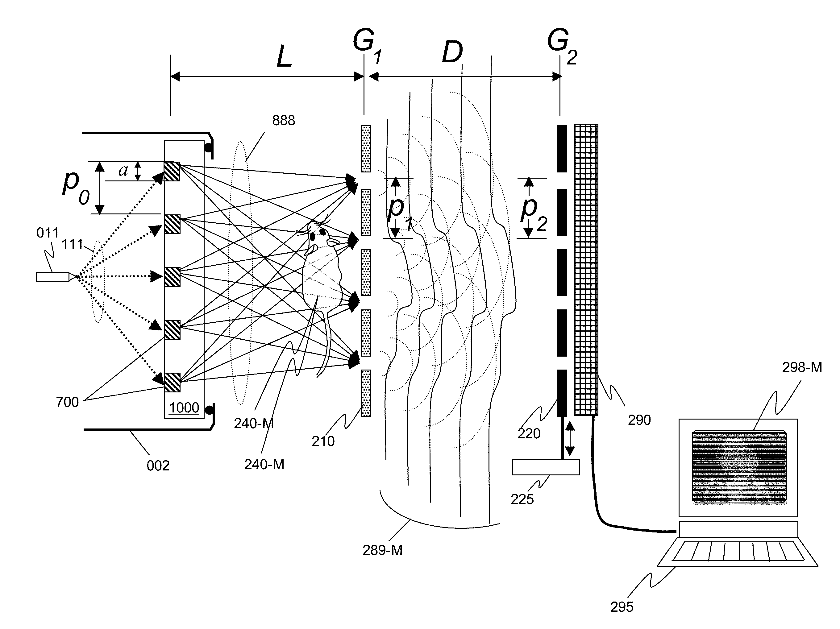
[0093]One embodiment of the invention disclosed herein is an x-ray phase-contrast imaging (XPCI) system as illustrated in FIG. 9. The system bears some similarity to the prior art Talbot-Lau interferometer, in that it comprises a beam splitting grating G1 210 of period p1 that establishes a Talbot interference pattern, and an x-ray detector 290 typically comprising an array of sensors to convert two-dimensional x-ray intensities into electronic signals.

[0094]The beam splitting grating G1 210 may be a phase grating or a transmission grating, and may comprise 1-D periodic patterns (linear gratings), or may comprise more complex 2-D structures such as a grid that is periodic in two orthogonal directions.

[0095]The system may also comprise an analyzer grating G2 220 of period p2 that may be placed in front of the detector to form additional interference fringes, such as Moiré fringes. The system may additionally comprise a means 225 to ...


PUM

PropertyMeasurementUnit
angleaaaaaaaaaa
wavelengthaaaaaaaaaa
periodic structuresaaaaaaaaaa

Abstract

Periodic spatial patterns of x-ray illumination are used to gather information about periodic objects. The structured illumination may be created using the interaction of a coherent or partially coherent x-ray source with a beam splitting grating to create a Talbot interference pattern with periodic structure. The object having periodic structures to be measured is then placed into the structured illumination, and the ensemble of signals from the multiple illumination spots is analyzed to determine various properties of the object and its structures. Applications to x-ray absorption / transmission, small angle x-ray scattering, x-ray fluorescence, x-ray reflectance, and x-ray diffraction are all possible using the method of the invention.

Description

CROSS-REFERENCE TO RELATED APPLICATIONS[0001]This patent application is a continuation-in-part of U.S. patent application Ser. No. 14 / 527,523, filed Oct. 29, 2014 and entitled “X-RAY INTERFEROMETRIC IMAGING SYSTEM”, which claims the benefit of U.S. Provisional Patent Application Nos. 61 / 898,019, entitled “X-ray Phase Contrast imaging System” and filed on Oct. 31, 2013; 61 / 901,361, entitled “An X-ray Source Consisting of an Array of Fine Sub-Sources” and filed on Nov. 7, 2013; and 61 / 981,098 entitled “Two Dimensional Phase Contrast Imaging Apparatus” and filed Apr. 17, 2014, all of which are incorporated herein by reference in their entirety. The present application additionally claims the benefit of U.S. Provisional Patent Application No. 61 / 987,106, filed on May 1, 2014 and entitled “METHODS OF REDUCING SCATTER RADIATION USING TALBOT EFFECT”; 61 / 989,743, filed on May 7, 2014 and entitled “Methods of Improving Detector MTF and DQE and Reducing Scatter Background of an X-ray Imaging ...

Claims


Application Information

Patent Timeline
Patent Type & Authority Applications(United States)
IPC IPC(8): G01N23/20G01N23/201
CPCG01N23/201G01N23/20075A61B6/4007A61B6/4291A61B6/484A61B6/508G21K1/02G21K2207/005H01J35/08H01J2235/086
Inventor YUN, WENBINGLEWIS, SYLVIA JIA YUN
Owner SIGRAY INC
Why Eureka
Try Eureka