Reticle pod with cover to baseplate alignment system

a technology of reticle and base plate, applied in the field of container, can solve the problems of reticle to a degree sufficient to seriously affect any end product, unsatisfactory final product quality, and unsatisfactory contact between reticle and other surfaces during manufacturing, processing, transportation or storage, etc., to achieve tighter dimensional control of pin placement, reduce the generation of particulates, and enhance shock and vibration isolation

Active Publication Date: 2015-09-24
ENTEGRIS INC
View PDF10 Cites 11 Cited by
  • Summary
  • Abstract
  • Description
  • Claims
  • Application Information

AI Technical Summary

Benefits of technology

[0008]Various embodiments of the invention are directed to alignment structures that have reduced area contact between components that may be in contact during placement of the cover onto the base for closure of an inner pod of an EUV reticle carrier.
[0011]Various embodiments of the present invention provide advantages in allowing for tighter dimensional control, thus limiting sliding contact during axial motion between the cover and base. In some embodiments, an alignment pin is pressed into a machined pocket, replacing the larger area alignment surfaces that were previously clamped onto the cover using fasteners. Another advantage is the reduction in the number of components, screws, mating surfaces, grooves and crevasses, all of which can trap particulates.
[0012]Structurally, in one embodiment, the cover and base of the outer pod utilize resilient seals providing a hermetically sealed first enclosure. The inner pod can be configured with a base portion configured as a planar surface with reticle support structure and reticle constraint structure extending therefrom. A cover portion of the inner pod engages with the base portion to define the secondary enclosure and also engages the top surface of the reticle. The cover and base portion of the inner pod can provide a hermetic seal such as by an elastomeric member or by non-elastomeric seals, e.g., a seal zone comprising hard planar surface to hard planar surface contact, or can have a restricted opening, an elongated gap extending substantially around the periphery of the secondary pod to reduce pressure shock waves and inhibit particles without a hermetic seal.
[0013]Additionally, the cover and base of the inner pod can be dimensioned to complement each other when aligned and engaged. The cover and base can each be provided with hard planar surface seal zones on the bottom surface and the top surface, respectively, such that when the cover and base are aligned and engaged, the bottom of the cover to the top of the base, the seal zones mate and the inner pod is hermetically sealed. In one embodiment, the cover of the inner pod is provided with a through hole into which a locating or alignment pin is disposed. The base can be provided with a guide recess to receive the distal end of the alignment pin. When aligned and engaged, the alignment pin works to prevent or limit lateral motion between the cover and the base thus inhibiting particulate generation.
[0017]Advantages of various embodiments of the invention is to provide tighter dimensional control of pin placement due to the alignment pin being pressed into a machined through hole or blind hole, while limiting the number of components, screws, grooves, crevasses and mating surfaces that can trap particulates. Enhanced shock and vibration isolation to the reticle, as well as reducing the generation of particulates due to the axial motion of the cover against the base, can also be realized. Various embodiments of the invention can also provide a reticle inner pod that is easily opened without undue motion and operations that can cause particulate generation.

Problems solved by technology

Because of the tiny size of the critical elements of modem integrated circuits, the operative surface of the reticle (i.e. the patterned surface) is kept free of contaminants that could either damage the surface or distort the image projected onto the photoresist layer during processing, both of which lead to a final product of unacceptable quality.
Considering the severe impact of particulates on semiconductor fabrication, unnecessary and unintended contact between the reticle and other surfaces during manufacturing, processing, shipping, handling, transport or storage is highly undesirable in view of the susceptibility of the reticle to damage to the delicate features on the patterned surface due to sliding friction and abrasion.
Also, any particulate contamination of the surface of the reticle can compromise the reticle to a degree sufficient to seriously affect any end product obtained from the use of such a reticle during processing.
Sliding friction between the reticle and the container and between the components of the container are sources of contaminating particulates.
Also, it is now known that gases and minute quantities of moisture can escape from the polymer materials used in reticle containers, such can cause haze and crystal growth on reticles damaging same.
For example small particles that are not big enough to cause a problem in conventional photolithography can be a significant problem in EUV photolithography.
Also, EUV photolithography can be performed under a vacuum which can make outgassing and / or moisture desorption from container components an issue, particularly when the components are polymers.
A concern is that particulate generation and entrapment that heretofore was tolerated in reticle pod carriers can become problematic in the context of carriers containing reticles for EUV photolithography use (e.g., particles generated between vertically sliding surfaces when the cover is mounted to the base, and particles entrapped between fasteners and fastened surfaces).

Method used


Image

  • Reticle pod with cover to baseplate alignment system
  • Reticle pod with cover to baseplate alignment system
  • Reticle pod with cover to baseplate alignment system

Examples


Embodiment Construction

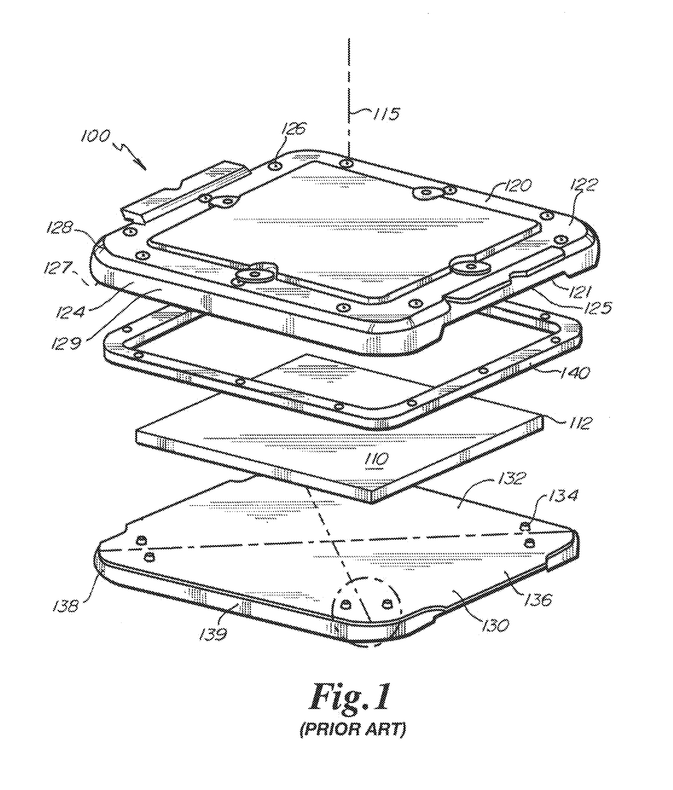
[0031]Referring to FIG. 1, a reticle container or inner pod 100 of the prior art is depicted. The inner pod 100 is configured, for example, as a reticle pod container, such as disclosed by Kolbow and Gregerson. The inner pod 100 generally includes a cover 120 capable of sealingly mating with a base 130 to define a hermetically sealed enclosure that holds a reticle 110 for storage, transport, processing and shipping. In FIG. 1, an alternate rigid seal ring 140 is shown as provided between the cover 120 and the base 130. The rigid seal ring 140 attaches to the cover 120 thus sealing the cover 120 to the base 130 by way of the rigid seal ring 140. The inner pod 100, seal ring 140 and reticle 110 are concentric about a central axis 115 that defines an axial direction.

[0032]The reticle 110 is located and supported near each of its corners on reticle contact members 134 mounted to the base 130. The reticle contact members 134 are mounted to the base 130 in a manner known in the art. The i...


PUM

PropertyMeasurementUnit
structureaaaaaaaaaa
radiusaaaaaaaaaa
metallicaaaaaaaaaa

Abstract

An alignment system for aligning the cover and base of an inner pod of a reticle carrier. The cover and base can each be provided with hard planar surface seal zones on the bottom surface and the top surface, respectively. The cover of the inner pod may be provided with a through hole or a blind hole into which an alignment pin is disposed. The base is provided with a guide recess to receive the distal end of the alignment pin. The alignment pin operates to limit contact surface area between the cover and the base during that is in sliding contact, thus inhibiting particulate generation. Low particulate-generating materials, such as stainless steel or polyamide-imide, can also be utilized to further reduce particulate generation. Furthermore, the cover and base can each be unitary without need for fastening components thereto, thereby eliminating clamped surfaces that can entrap and subsequently shed particulates.

Description

FIELD OF THE INVENTION[0001]This invention relates generally to a container for storage, transport, shipping and processing of fragile devices such as photomasks, reticles and wafers. More specifically, the invention relates to alignment of extreme ultraviolet (EUV) pods.BACKGROUND OF THE INVENTION[0002]One of the process steps commonly encountered in the fabrication of integrated circuits and other semiconductor devices is photolithography. Broadly, photolithography involves selectively exposing a specially prepared wafer surface to a source of radiation using a patterned template to create an etched surface layer. Typically, the patterned template is a reticle, which is a very flat glass plate that contains the patterns to be reproduced on the wafer. Typical reticle substrate material is optically clear quartz. Because of the tiny size of the critical elements of modem integrated circuits, the operative surface of the reticle (i.e. the patterned surface) is kept free of contaminan...

Claims


Application Information

Patent Timeline
Patent Type & Authority Applications(United States)
IPC IPC(8): B65D85/48H01L21/673B65D43/02B65D25/10B65D25/14
CPCB65D85/48B65D25/10H01L21/67359B65D43/02B65D25/14G03F1/66H01L21/67353H01L21/67373H01L21/67383H01L21/67386Y10T29/49895
Inventor LYSTAD, JOHNKOLBOW, STEVEN P.
Owner ENTEGRIS INC
Why Eureka
Try Eureka